Electronics for ILD MPGD-TPC readout
Electronics for ILD MPGD-TPC readout . Madhu Dixit TRIUMF & Carleton University. CERN, October 2009. Rise time for a single cluster determined by electron transit time in the induction gap. GEM charge preamp pulse characteristics. GEM 1. GEM 2. Anode readout pads.


Electronics for ILD MPGD-TPC readout
E N D
Presentation Transcript
Electronics for ILD MPGD-TPC readout Madhu Dixit TRIUMF & Carleton University CERN, October 2009
Rise time for a single clusterdetermined by electron transit time in the induction gap GEM charge preamp pulse characteristics GEM 1 GEM 2 Anode readout pads Madhu Dixit
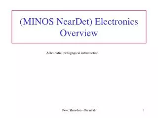
Rise time for a single clusterdetermined by electron transit time in the induction gap GEM charge preamp pulse characteristics Ar:CO2/70:30 200 MHz Aleph preamp 3.4 mm induction gap, Vdrift =69 μm/ns 4.5 keVxrays – collimated source in centre Charge collecting pad Induced pulses on neighboring pads tRise(calculated) = 49 ns (transit time) + 40 ns (preamp rise time) In agreement with experiment Madhu Dixit
GEM readout – typical parameters • Example: T2K gas, 2 mm induction gap • Eind ≈ 3 kV/cm, vdrift= 26 μm/ns • Rise time for a single cluster • trise ≈ 100 ns [77 ns + 30 ns (charge preamp risetime) • For a single cluster, the GEM signal rise time is relatively fast - about 50-100 ns, depending on gas, drift velocity and induction gap. • The Micromegas charge signal is due to ion drift, but rise times are similar to those for GEMs. Madhu Dixit
Signal characteristics for ILC TPC • All tracks originate for the collision vertex • 18-20 clusters (av. 50 electrons) for ~ 6 mm long pads • Track angle range 90< < ~10. • Tracks near 90 have the maximum drift ~200 cmTPC with T2K gas at 230 V/cm • Longitudinal diffusion 226μm/√cm, vdrift = 76 μm/ns • σChargesignal = 3.4 mm for tracks at 90 • Track charge signal collection time ~185 ns, the time to collect ~ 90% of the charge • Similar for small angle tracks near 10 • Add ~100 ns for intrinsic detector & electronics rise time. • To get 100 μm ILC TPC resolution, integration time of ~ 300 ns will be needed Madhu Dixit
Conventional ~ 100 ns peaking -TPC pulse processing Preamp charge pulse Shaper response Τ ≈ 2μs We decided to digitize charge pulse directly toget full electron signal MPGD2009 Madhu Dixit Madhu Dixit
A geometrical way to use wide MPGD pads with precision Finding the avalanche position on a proportional wire Avalanche x1 x1 Amp 2 Amp 1 Charge division on a proportional wire Telegraph equation Deposit point charge at t=0 Solution for charge density (L ~ 0) Generalize charge division to charge dispersion in 2D Finding the avalanche location on a MPGD resistive anode surface Telegraph equation 2-D generalization Solution for charge density in 2-D Madhu Dixit
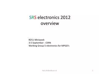
Charge dispersion in a MPGD with a resistive anode • Modified GEM anode with a high resistivity film bonded to a readout plane with an insulating spacer. • 2-dimensional continuous RC network • Point charge at r = 0 & t = 0 disperses with time. • Time dependent anode charge density sampled by readout pads. • Equation for surface charge density function on the 2-dim. continuous RC network: (r) Q (r,t) integral over pads mm ns r / mm M.S.Dixit et.al., Nucl. Instrum. Methods A518 (2004) 721. Madhu Dixit
B = 5 Tesla Cosmic ray tests at DESY (Nov-Dec 2006) Madhu Dixit
Electronics with charge dispersion • Integration time with charge dispersion is larger ~ 500 ns • Will depend on resistive readout RC Madhu Dixit
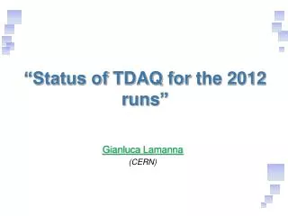
Resolution comparison: Old Method Vs average(700ns) Old Method 3652/17669Flat 50 µm Resolution Independent of z over 15 cm. New method 5663/17669 Flat 40 µm Resolution Independent of z. Madhu Dixit
Simulating the T2K with charge dispersion ( 8 mm x 8 mm pads) Anode surface resistivity 150 K/, dielectric gap = 75 m, K = 2 Track at z = 175 mm, x = 0, = 0 (uniform ionization) (ns) (ns) Pulses with very similar rise/fall times give 0 50 m for 2 x 6 mm2 pads Madhu Dixit
T2K TPC with charge dispersion readout - Simulated PRF 8 x 8 mm2 pads Pad response function Relative amplitude -20 -10 0 10 20 (mm) Madhu Dixit
SLHC Micromegas Muon chambers Capacitance 100 pF/cm^2 for 100 micron gap Strip width = 1 mm = 0.1 cm Assume 50 cm long strips = > Area = 5 cm^2 => capacitance 500 pF Will need to use MOSFET, since one can get better trans-conductance => faster risetime at larger capacitance MOSFET can be incorporated readily as part of ASIC, and can be made with radhard process Will need big MOSFET. One can live with that since high density readout is not needed Front-end preamplifier risetime better than 100 ns under these conditions For charge dispersion, risetime will determine pulse pair resolution in case of pulse pileup on long strips Consider area of 2 strips = > 10 cm^2 for pileup considerations Muon chamber rates 1E4/(sec.cm^2) max Count rate for 10 cm^2 area => 1E5/sec =0.1 hit/micro.sec = 10 micro.sec between hits Assume resolving time = 100 ns nbar = average rate per 100 ns = 0.01 P(n) = exp(-nbar). (nbar)^(n)/n! P(0) ~ 0.99 P(1) ~ 0.01 P(2) ~ ~0.01*0.01/2 Pile up probability ~ 0.01 => 1% 1% of hits will be unresolved at this rate. Resolution achievable should be better than 100 microns Madhu Dixit