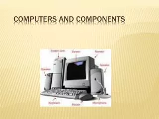
Infrastructure and components
Infrastructure and components. Cable. The cable and components used in structured cabling systems is defined in the standards EIA/TIA 568 x There are a number of different levels of cables and components known as Catagories ISO 11801

Infrastructure and components
E N D
Presentation Transcript
Cable • The cable and components used in structured cabling systems is defined in the standards • EIA/TIA 568 x • There are a number of different levels of cables and components known as Catagories • ISO 11801 • There are a number of different levels of cables and components known as Classes
Categories Specified in TIA/EIA 568 X (i.e. In various 568 standards) Cat 1: Previously used for POTS telephone communications, ISDN and doorbell wiring. Cat 2: Previously was frequently used on 4 Mbit/s token ring networks. Cat 3: used for data networks using frequencies up to 16 MHz. Historically popular for 10 Mbit/s Ethernet networks. Cat 4: Provided performance of up to 20 MHz, and was frequently used on 16 Mbit/s token ring networks. Cat 5: Provided performance of up to 100 MHz, and was frequently used on 100 Mbit/s Ethernet networks. May be unsuitable for 1000BASE-T gigabit ethernet. Cat 5e: Provides performance of up to 100 MHz, and is frequently used for both 100 Mbit/s and Gigabit Ethernet networks. Cat 6: Provides performance of up to 250 MHz, more than double category 5 and 5e. Cat 6a: Provides performance of up to 500 MHz, double that of category 6. Suitable for 10GBase-T.
Categories • Cat 1: Currently unrecognized by TIA/EIA. • Cat 2: Currently unrecognized by TIA/EIA. • Cat 3: Currently defined in TIA/EIA-568-B. • Cat 4: Currently unrecognized by TIA/EIA. • Cat 5: Currently unrecognized by TIA/EIA. • Cat 5e: Currently defined in TIA/EIA-568-B. • Cat 6: Currently defined in TIA/EIA-568-B. • Cat 6a: Currently defined in ANSI/TIA/EIA-568-B.2-10.
Category & data networks history • CAT3 • 10Mbit/s networks • CAT4 • Developed for increased bit rates but was superseded by CAT5 • CAT5 • 100MHz bandwidth easily carried 100Mbits/s • CAT5e • Was developed because a badly installed CAT5 system could not carry Gigabit Ethernet • CAT6 • Easily carries Gigabit ethernet, future proofs network • CAT6a • Designed to carry 10 Gigabit Ethernet
Classes • Specified in ISO 11801 • Class A: up to 100 kHz (category 1) • Class B: up to 1 MHz (category 2) • Class C: up to 16 MHz (category 3) • Class D: up to 100 MHz (category 5e) • Class E: up to 250 MHz (category 6) • Class F: up to 600 MHz (category 7)
Twisted pair • Two conductors are wound together to cancel out EMI • From external sources (entering cable) • From crosstalk (leaving cable) • The two wires typically carry equal and opposite signals (differential mode) • Noise on the pairs is mostly cancelled out • Each wire have similar amounts of EMI • EMI is 180 degrees out of phase with each other • Usually each pair has a different twist ratio
Primary Colours • White • Red • Black • Yellow • Violet • Secondary Colours • Blue • Orange • Green • Brown • Slate (grey) 25 pair cable
Telecommunications outlet • Also known as a TO • Standard specifies RJ45 connector • Must be wired T568A or T568B
IDC • Insulation displacement connector • Connector that pierces the insulation on a wire to make the connection • Removes the need to strip the wire before connecting • Must be wired T568A or T568B • Cold Welds materials together ???? Comparing an IDC connection (LH) with a crimped connection (RH) www.ami.ac.uk
Telecommunications outlet 2 • At least one should be • 4 Pair 100 OHM UTP • The other can be: • 4 Pair 100 OHM UTP OR • 2 Pair 150 OHM STP OR • 2 Strand, 62.5/125 multimode optical fibre
1 2 3 4 5 6 7 8 1 2 3 4 5 6 7 8 1 2 3 4 5 6 7 8 V V V V V V 3 1 2 4 2 1 3 4 V V T568A and T568B pinouts 1 2 3 4 5 6 7 8 T568A T568B
To clear any confusion • TIA-568-A and TIA-568-B are referring to the ANSI/EIA/TIA-568-A and ANSI/EIA/TIA-568-B wiring standards • T568A is a jack wiring pattern, one of the two in the standards; the other is T568B • T568A • Used in America • T568B • Used in Europe
Cable types • The standard recognises the following cable types • 4-pair 100 Ω unshielded twisted-pair (UTP) or screened twisted-pair (F/UTP) • 4-pair 100 Ω fully shielded twisted-pair (S/FTP) (ISO/IEC 11801:2002 only) • 2-fiber (duplex) 62.5/125µm or 50/125µm • 62.5/125µm USA standards • 50/125µm & 62.5/125µm European standards • Duplex SC connectors • Multi-unit cables are allowed, • Must satisfy the hybrid/bundled cable requirements of TIA/EIA-568-B.2, ISO/IEC 11801:2002 • Under carpet cabling is no longer recognized by that standard ISO/IEC 11801:2002
Work area • Work area equipment and cables covered by 568-B.1 and 11801:2002 • Work area cables to be a maximum of 3m • Exception to the 3m length discussed later • 2 telecommunications outlets per work area minimum • Patch leads are the same Category as the cabling
1st outlet Must be a 4 pair twisted pair cable Shielded Unshielded Category 6 is recommended 2nd outlet can be either A 4 pair twisted pair cable Shielded Unshielded A pair of multimode optical fibres Work area II
Customer Premises Equipment • Equipment Cord • Patchcords/cross-connect jumpers, including equipment cables/cords, should not exceed 5m (16 ft.).Note: ISO/IEC 11801:2002 specifies a max. patchcord/ cross-connect length of 5m (16.4 ft.), which does not include equipment cables/cords. • Horizontal cable 90m (295 ft.) max. total • Transition point of consolidation point(optional) • Telecommunications outlet/connector (TO) • Work Area (WA) Equipment cord
Other Rules • Bridged taps and splices are not allowed • Fiber splices are allowed for fiber optic cables • Application specific components shall not be installed as part of the horizontal cabling • eg. splitters, baluns • Cabling shall be configured in a star topology
Patch leads and equipment cords • Maximum combined length of 10m • Parts b,c & g • Maximum copper link length 100m • 90m + cords (10m)