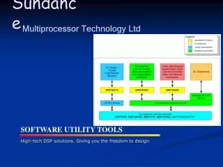
Sundance Multiprocessor Technology
Sundance Multiprocessor Technology. SMT702 + SMT712. Organization:. Introduction to SMT702 High-speed ADC Introduction to SMT712 High-speed DAC FPGA Configuration (SMT702/SMT712) Sundance Firmware Model SMT702 Firmware Overview SMT712 Firmware Overview SMT702 Clocks and Resets

Sundance Multiprocessor Technology
E N D
Presentation Transcript
Sundance Multiprocessor Technology SMT702 + SMT712
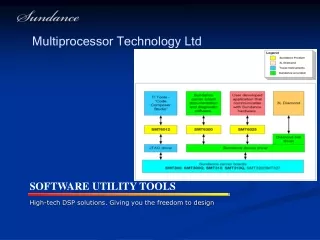
Organization: • Introduction to SMT702 High-speed ADC • Introduction to SMT712 High-speed DAC • FPGA Configuration (SMT702/SMT712) • Sundance Firmware Model • SMT702 Firmware Overview • SMT712 Firmware Overview • SMT702 Clocks and Resets • SMT712 Clocks and Resets • The DDR2 ‘FIFO’ Controller • Host PC Software: SMT7026 • Practical Time: Questions, Help, Suggestions...
SMT702 High-speed ADC • PXIe, 3U format (32bit PXI an option) • 4- lane, up to 8-lane connected • Most controllers do not support 8... • Dual 8bit ADC’s, up to 3Gsps (DDR mode) • AC-coupled • Serial configuration • Calibration feature • Typical BER = x10 to the -18 • CLKIN range = 500MHz – 1500MHz • Therefore (DDR) Fs = 1GHz – 3GHz • Can be synchronized to same sampling time • PLL +VCO with Ref. lock Clock circuit • External clock/Internal clock • 3GHz(1.5GHz) or 1.5GHz(750MHz) when internal (x1 or x1/2) • Reference clock in (software select) • External • 10MHz backplane • 100MHz backplane • Reference clock out
SMT702 High-speed ADC • Trigger • Internal (PXIe backplane) • External (front panel) • Flash + CPLD configuration • 1GB DDR2 memory x2 banks • 64bit wide, 128M deep • Max, 333MHz (250MHz default) • SHB x2 • LVTTL • 32bit + 3control +1Clock • SATA I x2 • RSL x1 • 4 data channels @ 250MB/s • Xilinx parallel JTAG • Xilinx FPGA • FFG1136-3 (fastest) • FX70T, LX110T (possibility for SX50T, SX95T) • All SMA connectors on front-panel
SMT712 High-speed DAC • PXIe, 3U format (32bit PXI an option) • 4- lane, up to 8-lane connected • Most controllers do not support 8... • Dual 12bit DAC’s, up to 2.3Gsps • AC-coupled • Serial configuration • Typical SFDR figures are close to 70dBs • Stable frequency synthesis without the need for an external clock input • DCM limitation of 120MHz, so minimum • sampling frequency is 960Msps • Can be synchronized to same sampling time • PLL +VCO with Ref. lock Clock circuit • External clock/Internal clock • Default sampling frequency = 2.3GHz • Reference clock in (software select) • External • 10MHz backplane • 100MHz backplane • Reference clock out
SMT712 High-speed DAC • Trigger • Internal (PXIe backplane) • External (front panel) • Flash + CPLD configuration • 1GB DDR2 memory x2 banks • 64bit wide, 128M deep • Max, 333MHz (250MHz default) • SHB x2 • LVTTL • 32bit + 3control +1Clock • SATA I x2 • RSL x1 • 4 data channels @ 250MB/s • Xilinx parallel JTAG • Xilinx FPGA • FFG1136-3 (fastest) • FX70T, LX110T (possibility for SX50T, SX95T) • All SMA connectors on front-panel
Sundance Multiprocessor Technology SMT702 + SMT712 FPGA Configuration
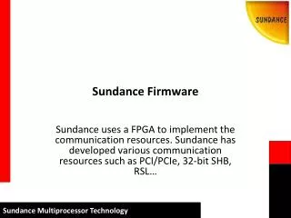
CPLD + Flash Configuration • The FPGA in both the SMT702 and SMT712 are configured at power up from a selectable address in on-board flash • A CPLD manages accessing the flash chip for configuration, and reading/writing from the Host – transparent from user • Flash size for both systems = 256Mbit
SMT6002 • The SMT6002 is the provided Host application used to access the flash chip for loading and deleting bitstreams via a connection block in the FPGA to the CPLD. • The tool will automatically detect the type of board and read the contents of the flash when launched. • The default firmware (at address 0x0) is read-only and so protected from deletion. This is so that even after custom bitstream booting, there is always a recoverable link to the flash for correction.
Changing the Flash Contents • Deleting • Select the bitstream to remove and press ‘Delete’. • There is a ‘Safe-erase’ option which will remove every bitstream in flash except for the default bitstream at address 0x0. • There is an option to remove the entire flash, but requires a modification to the Windows Registry. • Adding • After a bitstream path has been chosen, select a position in flash to load the bitstream. With the ‘Basic’ addressing mode chosen, the offset address will be adjusted automatically for the board accessed. Comments and Version information may be optionally loaded as well if desired.
Bitstream Configuration • The position offset address in flash can be chosen by switch selection (SW1). • SW1 has four, on/off switches integrated, but only toggle 1 and 2 are used. • The address to be booted can be counted in binary. • Position 0, (offset 0x0 default) is SW1(1 = off, 2 = off). • Position 1, (offset 0x800000) is SW1(1 = off, 2 = on). • Etc. • The FPGA can also be reconfigured after power up by selecting the bitstream, then ticking ‘Reconfigure FPGA from Flash’. Press ‘Commit’. • The approximate time to configure the FPGA from flash and be ‘alive’ to the Host is approximately 140ms.
Questions? The SMT6002 Help file can be found at: C:\Program Files\Sundance\SMT6002\SMT6002.chm