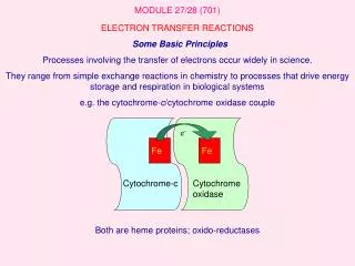
Introduction to Electron Optics: Understanding Wave-Particle Duality and Resolution Limits
This overview of electron optics explores the fundamental principles governing the behavior of electrons in microscopy. It investigates the reasons for using electrons, focusing on their unique wavelength properties and the impact of diffraction on resolution. Key topics include lens design, magnification, and the tradeoffs between resolution, magnification, and contrast in electron microscopy. Also discussed are common aberrations like spherical and chromatic aberration. This concise introduction is valuable for anyone interested in the intersection of physics and imaging technology.

Introduction to Electron Optics: Understanding Wave-Particle Duality and Resolution Limits
E N D
Presentation Transcript
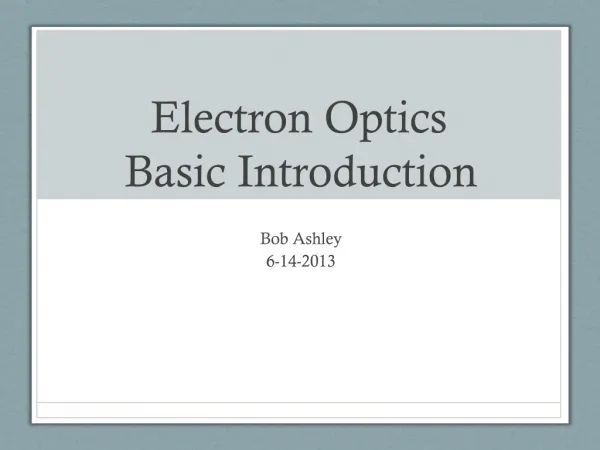
Electron Optics Basic Introduction Bob Ashley 6-14-2013
Overview • Why electrons? • Wavelength and visible light • Effects of diffraction and resolution • Lens design • Defects and distortions • Magnification
Electron Duality • Electrons have a particle and wave nature • Wave and particle nature • Source
Why Electrons? • Wavelength (λ) • Measurement of sinusoidal wave distance peak to peak • Visible light small segment • Electrons wavelength dependent on velocity • 200kV scope 1.2 x 10⁻³ nm http://reich-chemistry.wikispaces.com/Fall.2008.MMA.Boyle.Timeline
The Wave • Radiate from source in widening circles • Diffraction phenomenon • Wave strike edge and bend • Interference of waves http://images.tutorvista.com
Phase Illustration of phase shift. The horizontal axis represents an angle (phase) that is increasing with time. • Difference between two waves having the same electrical degrees or time and having the same frequency are in phase. • Can interfere with other waves. • Constructive interference • Additive property of two waves • Destructive interference • Cancelling waves • Scattering • Wave deviation from trajectory with resultant wave phase difference • Coherent • Constant phase difference • Not necessary to be in phase • Incoherent • Multiple phases combine and cancel = Wikipedia Waves combine (constructive, coherent) = Waves combine 180° out of phase (destructive, coherent) = Waves that combine with varying phases nearly cancel out (incoherent addition) www.scribd.com/doc/27753743/Coherence-Incoherence-And-Light-Scattering
Diffraction • Waves interfere with the initial wave front • Appear to have a series of bright parallel bands or fringes • Fresnel Fringes freh-nell • Resolution is degraded • Edges fuzzy rather than distinct
Airy Discs • The airy discs are the ringed patterns of Fresnel fringes • When they overlap more difficult to discern two points as independent and thus resolution is poorer • Airy disc radius is the measurement of resolution • Point Spread Function Figure: Bizzola Electron Microscopy 1999 http://greenfluorescentblog.files.wordpress.com/
Some Math • The math behind resolution (radius of airy disc) • λ= wavelength, n= refractive index (what medium the wave is passing through glass etc.), α= aperture angle of lens 0.612λ r = ______________ n (sinα)
Resolving Power • Light microscope • r = 172 nm • Electron Microscope • r = .003 nm theoretical • r = .27 nm point to point in JEOL 2100 scope • Why?
The Holy Trinity • Resolution, Magnification, and Contrast • Tradeoffs • None can be fully actualized
The Holy Trinity Resolution, Magnification, and Contrast • Resolution • The ability to distinguish two closely placed entities that otherwise might appear as one Adobe.com
The Holy Trinity Resolution, Magnification, and Contrast • Magnification • The measure of the increase in diameter of a structure from it’s original size
Holy Trinity Resolution, Magnification, and Contrast • Contrast • The ability to distinguish differences in intensity values between bright and dark areas.
Contrast • Two types in electron microscopy • Amplitude contrast (scattering contrast) • Subtractive effect where various shades are evident by loss of electrons • Main source of most electron microscope contrast (except cryo) • Phase Contrast (interference contrast) • Interference of diffracted waves cause intensity differences due to loss of energy and the corresponding shorter focal points • Appear as bright ring or halo around the edge of an object • Fresnel ‘freh-nell’ fringe
Lenses and Magnification • Image formation in a lens • Same optical properties of light microscopes and electron microscopes • Double convex converging lens • Same optical properties of light microscopes and electron microscopes • Refraction Bizzola Electron Microscopy 1999 www.passmyexams.co.uk
Electromagnetic Lenses • Electrons move in helical pattern • Very influenced by magnetic fields • Mass is small and require “mean free path”- high vacuum Bizzola Electron Microscopy 1999
Resolution Limiting Phenomena • Electromagnetic lens defects • Spherical aberration • Chromatic aberration • Astigmatism • Beam coherence • Source of electron beam Wikipedia
Spherical Aberration • Due to geometry of electromagnetic lenses such that rays passing through the periphery of the lens are refracted more that rays passing along the axis • Circle of minimum confusion • Corrected in EM with apertures to eliminate some of the peripheral rays but results in decrease aperture angle and therefore resolution This is Cs programs for image processing 2.0 mm in 2100, constant http://electron6.phys.utk.edu/ Bizzola Electron Microscopy 1999
Chromatic Aberration • Distortion in lens in which there is a failure to focus different wavelength rays to converge on same point. • In light it’s the different color wavelengths • In electrons shorter wavelength electrons are more energetic and have a longer focal length than longer wavelength electrons. • Results in enlargement of focal point similar to Airy disc • Minimized by ensuring stable voltage of source • Good vacuum • Thinner specimens • Electrons transmitted through specimen will change their energy and wavelength
Astigmatism • Radial blur results when a lens field is not symmetrical in strength but stronger in one plane and weaker in another • Only part of image will be in focus at a given time • Point would appear elliptical rather than spherical • Corrected by • Properly centered apertures • Stigmators of condenser and objective lens Nature Protocols 3, - 977 - 990 (2008)
Magnification in the Transmission Electron Microscope • Three magnify lenses in the electron microscope • Objective • Intermediate • Projector • image distance Mag = ___________________ object distance • Magnification is product of the individual magnifying powers of each lens MT = MO x MI x MP • Light microscope 1,000x • EM 1,000,000x • Useful magnification = resolution of eye (CCD) / resolution of lens system
The TEM…To Be Continued Bizzola Electron Microscopy 1999
Susan Hafenstein Pixel size
Calculating your Pixel size Knowing the size of each pixel in the digital image Used to produce a magnification bar and Measure objects For 3D cryoEM is is needed when determining the CTF and calculating the reconstruction
Information is imbedded in the ccd (in DM3 format – accessible by Digital Micrograph program)OR available in posted table on “Microscope magnifications and pixel sizes”ORYou can calculate from the known magnification used to record the image
Film 63,500 ---------- = 1.08 Angstrom / pixel 59,000 There are 25,400 microns/inch. 25,400 microns/inch divided by dpi = scan step size The Nikon Super Coolscan 8000ED scans at 4000dpi 25,400 microns/inch divided by 8000 = 6.35 micron 6.35 microns = 63,500 angstrom Divide 63,500 by the Magnification of microscope to get the pixel size
Calculation of Pixel Size From a CCD Image You have to know the actual pixel size of the CCD cameras and the magnification of your image.As an example: 15 microns = 150,000 Å.. camera pixel size (in Å) ------------------------------ = the pixel size at the specimen magnificationlevel
How big a box? Diameter Of object Box size (don’t forget to ‘feather’) 20 % Note: Or + 50%, or X2, or X3
Example:Picornavirus = 300Å+ 60 Åbox = 360Åif your pixel size is 2.14Å/pixelyou should select 168 pixel diameter for your box size
Workshop: Same data --- different programs Same program --- different data Beginners + intermediate + experienced