Troubleshooting refrigeration systems
Troubleshooting refrigeration systems. ►. 1.

Troubleshooting refrigeration systems
E N D
Presentation Transcript
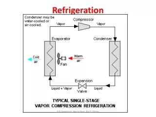
The design of industrial refrigeration systems is in theory straightforward. In practice, poorly tuned or malfunctioning components, fouling especially by oil, inert gas in the system, misplaced pipe lines, etc., can lead to capacity loss, control problems, frequent shut downs and other difficult to find and explain phenomena. This is typical for large custom made plants. Manufacturers of small standard units such as air conditioning OEMs, can usually iron out the problems before a chiller line goes into production. An industrial contractor usually does not have this luxury; the plant has to work immediately. General rules are hard to give as all systems are different and the troubleshooter has to be a bit of a detective. Below is an arbitrarily classification of possible malfunctions: ► Mechanical failures such as worn-out pumps, broken valves or compressor slides, i.e. all types of malfunctioning in machines (by definition, a machine has moving parts). ► Leakages in various components (a special case will be treated below). ► Construction errors such as faulty welds , components not made as conceived, wrong components, e.g. a solenoid valve closing instead of opening, a far too small valve, compressor, pipe, etc. ◄ ► General considerations, I. 2
► Fouling, corrosion and fatigue. ► Electrical, i.e. all parts of the electrical power circuit. ► Control, e.g. outright failures or wrong control algorithms. ► Faulty refrigerant, oil, brine or brine of wrong concentration. ► The above items are usually but not always clear-cut and the source of the trouble can usually be found and will not be treated here. However, sometimes more difficult to find troubles arise. The source can be any of the malfunctions above or simply that each component is faultless but together they do no work. ► The operator of the refrigeration plant has three interfaces to the system: the electrical power consumption, the condenser and the evaporator. We will deal here with troubleshooting the two latter, especially plate heat exchangers. ► The condenser pressure is too high, alternatively it increases and finally, the compressor HP cut out activates. ► The refrigeration system does not give the required capacity at specified conditions. “The evaporator is too small” is a frequent complaint. ◄ ► General considerations, II. 3
The pressure is too high but remains stable but sometimes the pressure continues to increase until the compressor HP cut-out is activated. Below are some frequent causes. ► Fouling on the water side, less frequent on the refrigerant side. ► A condenser which is too small, either by area, heat transfer coefficient or temperature difference. ► Higher load than foreseen. Double check with evaporator & oil cooler load and compressor load. Sometimes, the load of a refrigerant cooled oil cooler, which ultimately has to be removed by the condenser, is forgotten. ► A flooded condenser. A condenser can flood for four reasons: Pressure drop is too high in one of the parallel connected condensers, a misplaced equalization line, an obstruction at the exit or a refrigerant overcharge. ► Inerts in the vapour. ► Subcooling in the condenser. To be effective, there has to be a liquid level in the condenser but then the condensing area is decreased. The most serious consideration is that inerts can get trapped in the condenser. ► Obstruction of the exit. This usually less of a problem. As the condensate will flash to a pretty low temperature, the condenser could support a very large pressure drop. The drawback is that it might flash in the pipes before the expansion valve. Flashing refrigerant should be discovered by a sight glass, which always should be installed in the liquid line just before the expansion valve. ◄ ► 4 Troubleshooting condensers
An evaporator that doesn’t give the required capacity is sometimes a complaint from operators of refrigeration plants. The designer of the evaporator then patiently has to explain that an evaporator is a passive component, which can only give capacity presumed there is capacity, i.e. a sufficient refrigerant flow, on the other side. Below are some effects, which can lower the evaporation temperature, the most frequent claim: ► What happens if the evaporator really is too small? Too small in this respect is that either the area or the K-value is too small. The evaporator then produces less vapour than the comp-ressor can handle. The pressure falls, which increases the vapour volume, the evaporator produces more vapour because of the higher MTD, the capacity of compressor decreases and finally the system stabilizes at a lower evaporation temperature. ► What happens if there is not enough refrigerant entering the evaporator. As before, the flow is less than the compressor can handle, the temperature decreases and the MTD increases but this has no effect on the capacity and there is not sufficient refrigerant. The evaporator has to be in balance and it solves the MTD equation by superheating the vapour, effectively decreasing the MTD again. This is valid for a DX evaporator. A flooded flow evaporator is connected to a fairly large refrigerant charge and this can provide sufficient refrigerant to even out a temporarily refrigerant shortage but if this persists, the charge is consumed and the same occurs. ► A superheated refrigerant is a sure sign that an evaporator is operating below its possible capacity. ◄ ► 5 Troubleshooting evaporators, I.
►Oil in an ammonia system can foul an evaporator and has to be drained regularly. ► If water is present, oil will form a slurry, which fouls the evaporator. ► Water in ammonia will increase the evaporation temperature for a given pressure, thus decrease the capacity. By pumping down the system to a low temperature, most of the water remains as a liquid phase and can be drained from the system ► A separator placed too high. When the two-phase mixture enters the separator it is at the boiling point. When the refrigerant then descends to the evaporator, the pressure increases and the refrigerant is now subcooled. ► The K-value in the subcooling section is low. ► The refrigerant is preheated above the nominal evaporation temperatureand the MTD decreases. ► The return leg is likely to be long and high, giving a high pressure drop and thus a large temperature difference between evaporator and separator. ► All this contributes to decrease the capacity of the evaporator. This is especially important at low temperatures. With a liquid column of 10 meters, the subcooling of ammonia is about 3.9 K for an evaporation temperature of 0 °C. For an evaporation temperature of -40 °C, the subcooling increases to 17.6 K. That means that the evaporator will probably not work at all, the pressure at the evaporator is simply to large for the evaporation to take place. ► A far too low liquid level in a flooded flow system might not be able to lift the flow through the return leg. The result is low circulation and low capacity. ► Demisters, vapour superheaters and filters in the suction line obstruct the refrigerant flow and increases the difference between the evaporator and suction temperatures. ◄ ► 6 Troubleshooting evaporators, II.
► A too small pipe diameter or a too long pipe, valves, many bends and other obstructions in the return leg in a flooded system cause the exit pressure drop to increase and the result might be a large difference between the evaporator and separator pressures. As above, the effect increases with decreasing temperature. ► The difference between the evaporator and separator pressures is frequently a subject of contention between the evaporator and the system designer. ► Pumped flow in flooded system allows a designer a lot of options, which he maybe shouldn’t use, e.g. a too highly placed separator. That means a long subcooling zone and a high pressure drop in the return leg. ► Sometimes an ejector pump, driven by the flashing refrigerant, is inserted in the thermosiphon loop in order to improve the circulation. In order to do so, it has to be properly designed, something which is not always done. An ejector is unfortunately also a good oil atomizer and the oil can enter the channels and foul the surface. ► Distribution of the refrigerant and of high viscosity brines between parallel channels is a difficult problem especially for DX evaporator, somewhat less for flooded flow evaporators. ► Both the above problems can be revealed as unequal temperature distribution on the outside of the evaporator. A thermal camera or the formation of frost on the evaporator is a good help. ► Frost formation at start up of an evaporator is an excellent way of discovering distribution problems. ◄ ► 7 Troubleshooting evaporators, III.
► Distribution problem can also happen for water at high temperatures if the flow and thus the pressure drop is very low, more so in DX than in thermosiphons. Use multiple passes on the water side to increase the ΔP. ► Maldistribution can also cause freezing as the water cools unevenly, a problem in DX more than in flooded. ► A TEV before a DX evaporator has to be correctly placed. Unfortunately, a lot of valves give a well separated two-phase mixture and some evaporators are very sensitive to this. Don’t install bends after the TEV. ► There are some questionable control algorithms for some electronic EVs. One such, if not correctly adjusted, increases the superheat when the capacity increases. That means that the evaporation temperature has to be lower than necessary just to accommodate a too high superheat. ► The rated capacity for a TEV is usually given for around 11 K. If the evaporator superheat is 5 K, there is no possibility for the valve to give its rated capacity. Choose a larger valve. Troubleshooting evaporators, IV. ◄ ► 8
Propane condenser Propane to trucks Propane tank Propane from tanker Problem: The compressors cut out after a very short operating time. No particular information was given about the process it was going to operate in. Consequently it was it was designed as a normal condenser in a refrigeration system. An inspection at the site showed nothing particular – except the compressor cut-out. An analysis of the propane content was made with a butane analyzer and recalculated to propane. Discussion: A further check showed that it was not installed in a refrigeration system but used for condensing, after compression, of propane vapour from a tank farm when a tanker unloaded propane. When the tank fills up, vapour leaves. However, when the storage tank unloads, it has to be charged with nitrogen to keep the pressure above atmospheric, otherwise air might leak in and an explosion could occur. The propane recovery system thus has to be designed not for pure propane but for a propane-nitrogen mixture. Solution: The condenser was not designed for an inert gas condensation. Even small quantities of an inert gas increase the size of the condenser considerably. It had to be replaced with a considerably larger condenser. Comments: The results of the propane analysis are interesting. As the inert as content is very low, it means that the propane content is close to 100 %. Moreover, it was calibrated for butane. Analyzing a concentration close to 100 % with an uncalibrated analyzer could give large errors. It is not possible to get a reading closer than a couple of percent points.100 % propane means no inerts, 99 % means 1 % and that increases the condenser size considerably. It would have been better to have a nitrogen analyzer as the difference is large between 0 and 1 %. Fig. 1. Inert gas in a propane vapour. ◄ ► 9
Problem: The condenser could operate for only one of the two compressors. Once the second started, the pres-sure increased and cut out the compressors. Discussion: An inspection of the system showed nothing particular. The condenser seemed to be well drained to the LR. It had recently been opened, inspected and found clean. No physical obstruction was found in the adjacent pipes. However, a reading of the inlet water and the exit condensate temperature showed practically the same temperature. The cause could be either of two possibilities, a flooded condenser or inerts in the vapour, but it is difficult to determine which. The compressor manometers gave a hint. There were three undampened manometers of the same design, oil, suction and discharge. The oil was rock steady, the suction vibrated a little, while the discharge needle was almost impossible to see. A vibrating discharge manometer hints of inerts. Solution: Ammonia is easy to vent. A vent was placed on the LR and the vapour was fed into a bucket of ice water. If there is air in ammonia, it bubbles, pure ammonia doesn’t bubble. After half an hour bubbling, the manometer calmed down and became steady after four more hours venting. It was then possible to operate the plant with both the compressors. Comments: An undampened manometer is a valuable tool for inerts checks, especially with difficult to vent halocarbons. Fig. 2. Compressor cut-out. ◄ ► 10
Problem: The capacity of neither the evaporator nor the condenser was sufficient in this flooded evaporator system. Both had recently been opened, inspected and cleaned. The condenser shown here, exhibited large capacity and pressure oscillations and occasionally compressor cut-outs. Discussion: The condenser and its exit to the LR – normally a critical point – were correctly made. Venting was possible from the LR but no inerts were present. However, the separator was placed very high up, some ten meters and the eva-poration temperature was well below zero Celcius. This led to problems with the evaporator, see also Figure 10. The expansion valve was placed close to the separator and connected to the LR by a fairly large pipe. The height difference to the condenser meant that there was a very large danger of vapour flashing in the vertical pipe. When the valve closes, the condensate then flows back into the receiver – the large pipe makes it easy - and from this it floods the condenser. The system ammonia filling was pretty high, which compounded this problem. Solution: The separator was lowered and both the evaporator and condenser problems disappeared Comments: Placement of the expan-sion valve and LR above the condenser can be done but the risk for malfunc-tioning increases - especially venting will be difficult - and troubleshooting will be more complicated. It is thus not recommended, neither for flooded nor for DX evaporators. Fig. 3. A too high placed expansion valve. ◄ ► 11
Problem: This PHE was replacing a corroded S&THEs, equal to the two others, However, the PHE didn’t give the capacity. A substantially subcooled condensate indicated a flooded condenser. Discussion: The ΔP is higher in the PHE than in the S&THEs. Obviously, the ΔP from point A to C have to be the same regardless if the path is A ‑B1(2)‑C or A ‑ B3 ‑ C. At the exit of the condensers, the pressure is lower in B3 than in B1 & B2. The condensate lines form a communicating system with a lower pressure in one leg, B3. That causes a higher liquid column – h - to form in this leg. Unfortunately in this case, the condensate pipes connect just below the exits, the higher liquid column in B3 builds up in the plate channels, floods these and the effective area is decreased. Solution: The collector pipe was lowered and the liquid column is now created in the vertical pipe outside the PHE. ◄ ► 12 Fig. 4. Parallel connected condensers.
Problem: The plate condenser didn’t give the rated capacity. A substantially subcooled condensate indicated a flooded condenser. The difference to the previous case is that here there is only one condenser, not many in parallel. Discussion: The system was equipped with a “surge” LR. The condensate doesn’t pass through, it is just in communication to take up load variations. To facilitate this, it is connected to the condenser inlet via an equalization line. Vapour moves through this in & and out of the LR as the con-densate moves in and out. The vapour entering the condenser inlet from the LR should then re-condense. As the pressure is higher at the condenser inlet than at the exit, it is necessary with a liquid column to compensate for this ΔP. The total ΔP in two parallel legs should be equal. In this case, the equalization line was connected upstream a de-superheater with a fairly large ΔP and the resulting liquid column became high and flooded the condenser. Solution: Reconnection of the equalization line to immediately before the PHE drained the condenser. Comments: Misplaced equalization lines and poorly conceived LRs are a common source of condenser troubles. ◄ ► 13 Fig. 5. A misplaced equalization line.
Undersideof pipe Ambient temperature Equaliza-tion line To bulb Problem: The installation was a pretty normal direct expansion evaporator equipped with a standard thermostatic expansion valve with external equalization, but it simply didn’t produce any cooling at all. Discussion: A check with a thermal camera showed some interesting results. The first pictures were taken from the front side only as the back side was difficult to reach. The exit pipe, above marked “Ambient temperature” was just that, i.e. no cooling was discovered. Astonishingly enough, the pipe marked “Cold pipe underside“ several meters after the TEV, became blue on the picture somewhat after the start, indicating a low temperature. The part just behind the PHE could not be seen. The equalization line was ambient temperature. The result was that baffling that an attempt was made to take pictures from the back side, where the bulb and the equalization line connection to the exit pipe could be seen. The start up showed the sequence below. At first everything was orange, i.e. ambient temperature. Then: - Exit of EQ line. The connection was slowly turning blue. - Below EQ connection. A little later, the bottom part of the pipe below the connection turned blue. - Further down the pipe. The blue colour slowly spread downwards. A check of the valve showed that there was a leakage in the packing box. Moreover, the equalization connection at the suction gas pipe was very small – high ΔP. Thus: - HP condensate leaks through the packing box into the equalization chamber. - The diaphragm is pressed down and the valve closes. - No more refrigerant leaves the normal exit. - Liquid condensate flows through the EQ line to the connection, expands and cools. - Liquid cold refrigerant drops down to the pipe bottom and cools this. Solution: The TEV was exchanged and everything worked. Comments: A thermal camera is an extremely useful tool when troubleshooting. ◄ ► 14 Fig. 6. A broken expansion valve.
Oil drain. A. Ejector inlet (NH3 in a SWPHE) B. Pipe-in-pipe inlet (R134a in a CB). Problem: Both flooded flow evaporators above had injection of flashing refrigerant in the loop in order to increase the circulation. None of them gave the intended capacity. A. The low capacity was at least partly due to oil fouling on the ammonia side. B. This CB had stability problems and and occasionally reversed flow. Discussion: Injection of the flashing refrigerant in the circulation loop can improve the circulation if a properly designed ejector pump is used. The ejector in A was a home made design of questionable functionality. When A was dismounted, it turned out that there was a lot of oil in the evaporator, not astonishingly as an ejector is a good atomizer. A closer inspection of B showed that there was back flow of refrigerant through the drop leg back to the separator. The pipe-in-pipe design had no ejector function at all. It was easier for the vapour to pass back through the drop leg than through the evaporator. Solution: Both were redesigned as normal thermosiphons. A. The pipe was made slightly upwards inclining and with an oil drain at the lowest point. B. A soluble oil does not need an oil drain. Comments: An ejector design can improve the operation but a correct design is difficult to make. ◄ ► 15 Figure 7. Flooded flow evaporators with ejector.
To unit coolers Return from SWPHE To SWPHE Vertical separator SWPHE Pump station ► At the installation, there were probably both liquid lines at the roof top and vapour lines in the cold storage. ► Moreover, see the figure above; there were a number flooded flow unit coolers connected in parallel to the liquid evaporator. These units coolers were installed at least ten meter higher than the PHE. It is difficult, to say the least, to operate parallel units in general and different types at different heights can be close to impossible. ► Mechanical. Broken parts, forgotten tools, or metal pieces can get trapped but not unmovable and cause the noise. ► An expansion valve is sometimes, especiallyin DX systems, preceded by a solenoid valve. If pumpdown is made, the pipe after the sole-noid valve will be emptied of liquid refrigerant. When the solenoid valve opens, a liquid co-lumn with increasing speed moves towards the TEV, which easily can be damaged apart from the minor problem of noise. Install the solenoid just before the TEV. ► In a vapour line, e.g. for hot gas defrost, pas-sing through the cold storage, refrigerant can condense when the line is shut off. At restart, a high speed liquid plug can damage a valve. ► A liquid line, passing through a hot area or exposed to the sun, can be sufficiently heated for refrigerant to vaporize when theflow stops. Restarting the flow will cause a vapour plug to move with high speed along the pipe. The vapour can easily pass a valve but the subsequent liquid column can’t, i.e. damages and noise. ► If the pressure is suddenly increased, e.g. a hot gas defrosting, it can cause a (previous) low pressure vapour to implode. This is the same phenomena as cavitation. ► It is not unconceivable to imagine a unit cooler closing and the resulting liquid column in the vertical feeder pipe line flow down or refrigerant to evaporate, with ensuing noise, see Slide 3. ► However, the noise had a definite metallic quality. By using a time honoured method – putting an ear to the pipe at various loca-tions, it was possible to find the place with the strongest noise. It was at the upwards bend after the ammonia circulation pumps. Solution: The cause of the noise was not found until a year later, when the system was opened for maintenance. A broken valve stem had moved to the first upwards bend after the pumps. The liquid velocity was then insufficient to lift it further, it stayed at the bend, swirled around and made noise. Problem: Shortly after the installation of a new PHE evaporator – a flooded, forced flow system – loud bangs and noises were heard in the system. The source of noises in metal piping can be difficult to find but as the evaporator was the only new item it was the prime suspect. The evaporator was installed in a very large commercial cold storage. Discussion:Loud, sharp noise from an item with no moving parts is unlikely but then, where does the noise originate? There are a couple of causes for noise shown on the next page: ◄ ► 16 Figure 8. Bangs in a pumped flow evaporator..
Problem: A chiller manufacturer had problems with a custom made unit. The nominal temperature program was: 20 % Ethylene glycol +3 → -3 °C Propane of -8 +(5) ← -8 °C. The unit was assembled from parts pur-chased in some four different countries. At start-up the end temperature was about 10 K instead of the nominal 5 K Not surprisingly, all component manufac-turers claimed that their particular compo-nent was faultless and worked well in similar applications. The technical manager was helpless. Discussion: During a technical seminar, the manager understood that the valve was not correctly installed; he remembered that the valve was possibly installed before a bend. Solution: The valve position was changed the same day and nominal duty was obtained. Figure 9. An incorrectly installed thermostatic expansion valve. ◄ ► 17
Problem: This large ammonia thermosiphon installation in a chemical plant didn’t give the capacity. There was also a problem with hunting. Discussion: An inspection of the plant showed a very nice installation, everything – including the tightening bolts of the PHE – properly insulated and clad by aluminium sheets. Unfortunately there were hardly any instruments or sight glasses, the separator had as only instrumentation the pressure and the ammonia level. It was really a black box. A further inspection showed that there was no automatic oil drain and the drain point was from the separator rather than from just before the evaporator. Discussion with the contractor also revealed that the separator was full of baffles, guide vanes, pipe distributors for the flash gas, protection sheets and a demister. The final measured was taken six months later at the annual overhaul. It turned out that the angle valve was far too small and was ex-changed. This measure decreased considerably the difference between the evaporation and suction temperatures. The remaining difference was mainly due to the internals of the separator. The hunting also decreased. Comments: We here encounter three of the most frequent problems in a flooded installation. ► Oil drain. ►The difference between the evaporation and ►suction temperatures. ►A separator placed too high. Conclusion: If the large head is not necessary, place the separator as low as possible. The capacity of the evaporator in the system described inslide 3 improved when the separator was lowered. There are cases when the evaporator needs a large pressure drop but then, the entire thermosiphon loop has to be design for this and not only the evaporator. There was a strong suspicion that the pressure drop from the evaporator exit – the evaporation temperature, via the separator – the separator pressure – to the compressor suction connection – the suction pressure - could be very large. Unfortunately, a refrigeration vessel, as opposite to a chemical vessel, has no man hole. Inspection of the interior was not possible. The separator was placed very high, much higher than the evaporator required. That increases the subcooling zone, especially at low temperatures, -25 °C, in this installation. Solution: Two measures were taken at site. There was a possibility to drain the oil from a connection much closer to the evaporator than the original oil drain. Draining reveal quite a lot of oil in the system. This improved the capacity somewhat but not entirely. An try was made to measure the evaporation tem-perature. It had to be done outside the return leg. This is difficult, especially here, due to the solid insulation. As a reference, the separator tempera-ture was also measured in the same way. The re-sult confirmed the suspicion that the temperature difference was very large, i.e. the evaporation temperature was far above the suction temp. Keep the interior of the separator as simple as possible. You never know if it is built as conceived. Figure 10. Lack of capacity in a low temperature evaporator. ◄ 18