EC135 Helicopter
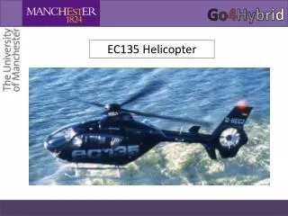
EC135 Helicopter. Introduction. EC135 helicopter one of the most commonly used light weight class helicopters Used within several CleanSky projects, both numerical and experimental studies. The most relevant to us being HELIDES.

EC135 Helicopter
E N D
Presentation Transcript
Introduction • EC135 helicopter one of the most commonly used light weight class helicopters • Used within several CleanSky projects, both numerical and experimental studies. The most relevant to us being HELIDES. • More detailed than the previous EC145 helicopter studied in the ATAAC project but will have many similar flow features to the EC135.
Geometry description • Includes both the fuselage, landing skids and empennage • More detail e.g windows, landing skids and the mast fairing
Experimental data • Still needs to be confirmed whether the experimental data can be shared, but should be several PIV windows, unsteady pressure probes across the surface as well as force loads on all the components
Modeling challenges • Capturing the complex geometry with a suitable quality grid (i.e limiting the number of skewed, high-aspect ratio cells). • Generation of affordable grids • Prediction of pressure-induced 3D separation on the fuselage (e.g can the RANS models in a hybrid framework correctly predict this). Do we need more advanced RANS models in a hybrid RANS-LES methodology?
Relevant modeling techniques Modeling options • URANS results have been shown to be very much dependent on the underlying model [1] and none of the models tested were able to correctly reproduce the PSD of the surface Cp. However this does not mean no URANS model can reproduce these. • Extensive thin, turbulent boundary layers make LES and WMLES unfeasible, therefore perfect for hybrid RANS-LES. Challenges • Achieving LES resolution in the wake of fuselage may be achievable but around the landing skids may be challenging. I.e very different turbulent scales around the helicopter • Considerable sensitivity to the underlying RANS model is expected because of the 3D pressure induced separation from the fuselage. • [1] C. Mockett, M. Fuchs, F. Le Chuiton and F. Thiele. Detached-Eddy Simulation for Helicopter Fuselage Aerodynamics. 6th European Congress on Computational Methods in Applied Sciences and Engineering (ECCOMAS), 2012.
Flow and boundary conditions • No-slip conditions for all walls • Inlet/outlet and symmetry for farfield boundaries. • Fully turbulent inflow conditions
Grids • HEXPRESS™grid (created by CFD Software GmbH): unstructured 32 million cells, provided in OpenFoam format. • Has shown very good numerical robustness, no need for ‘special numerical fixes’
Computational guidelines • It is recommended to initialize the solution with a RANS solution (using the same underlying RANS model), for improved stability and to enable analysis of RANS performance. • Mandatory time step of 1x10⁻⁴s, shown in [1] to be necessary for a CFL of less than 1 for the mandatory grid in LES regions. • Suggested 4 convective time unit (CTU) (based upon helicopter fuselage) initial transient time followed by 40 CTU’s for time averaging. Important to show plots of the averaging to prove a suitable statistical sample has been produced.
Required outputs and results • Time dependent surface pressure and force loads for each component (for spectra and statistical sample checking) • Cp,Cf to establish separation and transient lines (time-averaged and instantaneous). • Mean surface pressures and force and moment coefficients • Velocity vector, modeled & resolved turbulence (UU,VV,WW,UV etc) for the provided PIV plane windows. (time-averaged) • Some visualization of the flow and vortices, e.g Q or λ2 criterions • Animations of the flow structures and streamlines