Download
1 / 30
500 likes | 1.23k Vues
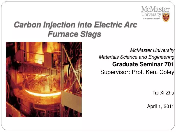
Carbon Injection into Electric Arc Furnace Slags. McMaster University Materials Science and Engineering Graduate Seminar 701 Supervisor: Prof. Ken. Coley Tai Xi Zhu April 1, 2011. Agenda. Introduction Literature reviews Experimental method and results Discussion of model and results

E N D
Carbon Injection into Electric Arc Furnace Slags McMaster University Materials Science and Engineering Graduate Seminar 701 Supervisor: Prof. Ken. Coley Tai Xi Zhu April 1, 2011
Agenda • Introduction • Literature reviews • Experimental method and results • Discussion of model and results • Future works
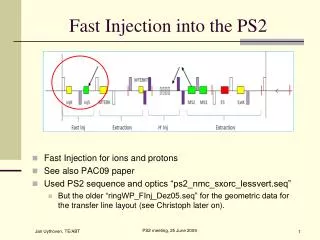
Introduction- Electric Arc Furnace(EAF) • EAF produces engineered steel from recycled scrap metal • Primary processes include: • Scrap charging • Pre-heating with burner and melting with electrical arc • Second charge • Carbon and oxygen injection • Tapping
Introduction- Slag Foaming • Carbon is injected to react with molten slags, it decreases iron oxides and optimize slag foaming • Protect electrode • Reduce noise • Increase furnace lining service life • Improve energy and thermal efficiency • Focused research in carbon/coal injected into EAF slags
Literature Reviews • Reaction of injected carbon with oxides in slags C(injected, s) + O (slag) = CO (g). Schematic representation of carbon-gas and slag-gas reaction (M. King Thesis 2009)
Literature Reviews • M. King (2009) developed model for the reaction of carbon particles injected into slag and it predicts total amount of carbon in the slag and rate of gas(CO) generation during carbon injection into EAF slags pCO2 is the equilibrium pressure of CO2 in bubble surrounding [atm] the carbon pcCO2 is the pressure of CO2 at the carbon-gas interface[atm]. 𝑛°C is initial number of moles Mi and ρi are molar mass and density of CO and CO2 respectively aO is equilibrium CO/CO2 partial pressure in slag 𝑅𝑝 is carbon particle injection rate [particles s-1] 𝑘𝑎 is rate constant for reaction at slag-gas interface [mol m-2 atm-1 s-1] t is carbon residence time in slag[s]
Literature Reviews • Foam index Σ – “how long can bubble survive” • It is intermediate parameter that helps us to understand foaming processing in EAF furnace, it was firstly defined by Ito and Fruehan(1989), in the unit of time(sec), and represented ideal average foam/bubble traveling time through foam layers. Δh - change of foam height Qg -gas flow rate - superficial gas velocity [m/s]
Literature Reviews • Development of foam index Σ Jiang and Fruehan (1991) Zhang and Fruehan (1995) Ghag et al. (1998)
Literature Reviews • Development of foam index Σ Lahiri-Seethanraman (2002) Morales et al. (2002) – Dynamic foam index
Literature Reviews • Critical bubble wall thickness proposed by J. van derSchaaf and Beerkens’ (J. Colloid Interface Sci., 2006) AH – Hamaker Constant (J) davg – average buble diameter σ - surface tension (N/m)
Experimental Method Carbon injection into EAF slags experimental setup (Thesis, M. King, 2009)
Experimental Results Slag foam height vs. superficial gas velocity
Discussions • Experimental results demonstrate that after a critical point, foam height continued to increase as a function of superficial gas velocity but at a much reduced rate. • . • This critical point is strongly dependent upon slags volume
Discussions • Assumption: • each gas bubble is spherical • Critical point happens when all molten slag is consumed • Particulate carbon is injected into slag at constant rate • Critical bubble wall thickness is average bubble wall thickness at steady state
Discussions Slag foam height vs. Bubble diameter
Discussions Slag foam height vs. bubble wall thickness
Conclusion • Increase in slag foaming with carbon injection rate is limited by slag volume • This phenomenon is likely caused by either an increase in the energy required to grow bubbles beyond a certain size or by the increased tendency to rupture of bigger bubble.
Improvement of M. King’s works • t < ∑ (foam index) t > ∑ (foam index) but < t_inj
Future Works • Improve previous work done by M. King • Extend theory of critical carbon injection point to other slag volumes
Acknowledge • Dr. K. S. Coley and Dr. G. A. Irons • Dr. S. Ray • Owen Kelly and Dr.KumarKrishnaposharody –experiments • Dr. F.Z. Ji (ArcelorMittal) and M. King- experimental and theoretical advice • Natural Sciences and Engineering Research Council of Canada (NSERC)
Thank You Inert your LOGO here Tai Xi Zhu Carbon Injection into Electric Arc Furnace Slags McMaster University