Download
1 / 12
120 likes | 215 Vues
Verify FHST mapping performance, calibrate gyro drift biases, and align FHSTs for accurate attitude determination. Ensure normal vehicle operations. Real-time data analysis and processing involved.

E N D
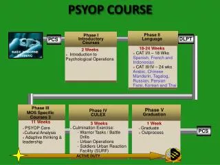
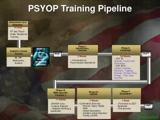
PCS SMOV-3B Review • Objectives • Overview • Activity Descriptions • Requirements
Return HST to Normal Science Operations Calibrate RGA drift rate bias and Initialize Attitude. Verify the FHST/FHST alignments and update if necessary. Monitor vehicle disturbances. Perform on-orbit modal test, if necessary. Objectives
Overview FHST FOV Check Gyro High and Low Mode Drift Rate Bias Calibration Attitude Initialization HST Release 0d 0h 0m Slew to BEA Region 0d 0h 40m FHST/FHST Alignment Calibration FHST Alignment changed? Normal Operation 0d 11h 0m Health and Safety SMS 1d 6h 15m No ScI SMS 2d 14h 30m Yes FHST/FHST Alignment Update RGA/FHST Alignment Calibration (contingency) FHST/FGS Alignment Calibration (contingency) Vehicle Disturbance Test Transfer Function Test (contingency) Note: Times shown are activity start times measured from HST release
Purpose: Verifies that the FHSTs are mapping normally and that the observations can be used for attitude determination (Req. J.10.4.8.1). Description: FHSTs will be commanded in real time to perform maps of their full FOV and the observations will be analyzed to determine if the FHST performance is adequate for subsequent activities (initial attitude and gyro bias determination, attitude initialization and RGA to FHST calibration). This activity is expected to last three hours. PCS-1: FHST Field of View Check
Purpose: Compute the initial low and high mode gyro drift rate biases, to reduce the vehicle low mode drift to less than .05 arcseconds per second. This will allow a return to normal vehicle operations (Req. J.10.4.8.2). Description: FHST maps are used to measure the vehicle attitude drift due to uncompensated gyro drift rate biases. There will be three FHST map periods with the gyro modes switched from high to low during the second map period. Attitudes computed from the first and second map periods will be used to determine the high mode drift rate bias, and attitudes from the second and third map periods will be used to determine the low mode drift rate bias. This real time activity is expected to last three hours. An additional three hours is needed for data processing, data validation, and Table Load generation. PCS-2: Initial Attitude and Gyro Drift Rate Bias Determination
PCS-3: Attitude Initialization Purpose: Determine the vehicle attitude using FHST observations and update the On Board quaternion. This activity is needed to return to normal operations (Req. J.10.4.8.1). Description: The FHSTs will be commanded in real time to perform a full FOV map. The observations will be used to compute an Attitude Reference Update that is uplinked to the On Board Computer. The duration for this activity is about one hour.
Purpose: Verify the FHST/FHST alignment prior to using the FHSTs for vehicle attitude updates (Req. J.10.4.8.3). Description: With the vehicle at a constant attitude each pair of FHSTs will be commanded in real time to perform a full FOV map. The observations from these maps will be used to compute an FHST/FHST alignment. This alignment will be compared to the pre-Servicing Mission alignment. If there is a change of 20 arcseconds or greater in the pitch or yaw components, a new alignment will be uplinked to the vehicle. This activity requires seven hours of data collection, and 24 hours of analysis time. PCS-4: FHST/FHST Alignment
Purpose: This is a contingency activity to calibrate a new set of gyros . This is required to maintain errors after a maneuver to less than one arcsecond per degree of slew (Req. J.10.4.8.4). Description: Six maneuvers are performed. Each maneuver is about one of the vehicle axes with a slew angle of + or - 90 degrees. Before and after each maneuver the FHSTs perform a map of their full FOV. This set of maneuvers is repeated approximately 24 hours later to verify the new calibration. This activity requires about 56 hours to complete. The maneuvers require 8 hours to execute. Approximately 24 hours are required to process the data and uplink Table Loads. Another 8 hours are needed for the verification slews and about 16 hours to process the verification data. This activity is implemented via an SMS proposal. PCS-5: RGA/FHST Alignment
Purpose: This is a contingency activity that allows the FHSTs to be realigned to the FGS system. This is needed to ensure that FHST updates following maneuvers will result in successful FGS guide star acquisitions. This activity will be performed if guide star acquisitions are failing. (Req. J.10.4.8.5) Description: FGS 3 will map out its FOV using coarse track astrometry observations while the FHSTs are mapping their FOVs. The FHST/ FGS alignment will be computed and Table Loads will be uplinked to the vehicle. The duration for this activity is 75 hours. The data collection requires 3 hours and the subsequent data processing requires about 48 hours. An additional 24 hours is needed to update the ground system and generate Table Loads for uplink to the vehicle. This activity is implemented via an SMS proposal. PCS 6: FHST/FGS Alignment
Purpose: The purpose of the Vehicle Disturbance Test is to characterize environmental disturbances acting upon the HST during normal operations. This activity was previously done after Servicing Missions to establish a signature for disturbance baseline of the vehicle. (Req. J.10.4.8.7) Description:The test consists of 12 orbits in a +V3 sunpoint attitude with solar arrays at 90 degrees and 5 orbits in a –V1 sunpoint with solar arrays at 0 degrees. The control law is commanded to use maneuver gains, and the gyros are commanded to low mode. Maneuver gains are removed at the end of the test. The +V3 sunpoint portion can be done during the BEA period. PCS 7: Vehicle Disturbance Test
PCS-8: Transfer Function Test Purpose: The Transfer Function Test (TFT) is an on-orbit modal test designed to measure HST system modal parameters (modal gains, modal damping ratios and system natural frequencies). The TFT will be performed if PCS analysis of post-SM3B flight data (such as the VDT) indicates that HST modal parameters significantly differ from pre-SM3B analytical models. Reductions in the HST attitude control system stability margins and/or increased vehicle jitter can occur when on-orbit modal parameters differ from modal parameters used in pre-SM3B analyses. (Req. J.10.4.8.8) Description: The TFT is a contingency test. The test consists of 9 orbits in the +V3 sunpoint orientation and 9 orbits in -V1 sunpoint. Prescribed forcing functions are applied via the RWAs and the responses are measured with the RGA gyros while the maneuver gain set control law is in effect and the gyros are in low mode.
J.10.4.8 Pointing Control Subsystem Verification Requirements J.10.4.8.1 The initial attitude shall be determined to an accuracy within .2 degrees using Fixed Head Star Tracker (FHST) data. J.10.4.8.2 The gyro drift rate bias shall be calibrated to within 0.05 arcseconds per second prior to the first guide star acquisition. J.10.4.8.3 The FHST/FHST alignment matrices shall be computed, using FHST observations at the initial attitude, to an accuracy of 5 arcseconds (1s). The FHST/FHST alignment matrices shall be updated if the change in the pitch or yaw alignment exceeds 20 arcseconds. The alignment computations will be further refined during normal operations to achieve accuracy comparable to the pre-Servicing Mission level J.10.4.8.4 The gyro-to-FHST alignment matrices shall be updated to an accuracy that reduces the attitude error following a vehicle maneuver to less than one arc-second per degree of slew. J.10.4.8.5 The PCS (Pointing Control System) shall acquire guide stars in fine lock. J.10.4.8.6 The vehicle jitter during periods of fine lock shall be measured. J.10.4.8.7 Perform a Vehicle Disturbance Test (VDT) to properly characterize the on-orbit system disturbances. J.10.4.8.8 Contingency activity of performing a Transfer Function Test (TFT) in case post-SM3B HST flight data suggests that HST system modal parameters significantly differ from pre-SM3B analytical models. SMOV PCS Level 3 Requirements