Chapter 10 Mobile Communication Systems
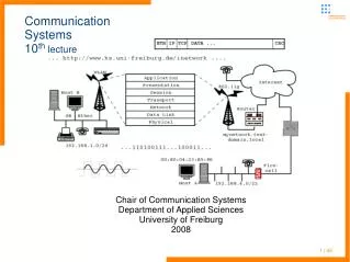
Chapter 10 Mobile Communication Systems. 曾志成 國立宜蘭大學 電機工程學系 tsengcc@niu.edu.tw. Cellular System Infrastructure. Base Station System. VLR. BTS. HLR. Visitor Location register. BTS. BSC. AUC. Home Location register. MS. …. Authentication Center. EIR. BTS.

Chapter 10 Mobile Communication Systems
E N D
Presentation Transcript
Chapter 10Mobile Communication Systems 曾志成 國立宜蘭大學 電機工程學系 tsengcc@niu.edu.tw EE of NIU
Cellular System Infrastructure Base Station System VLR BTS HLR Visitor Location register BTS BSC AUC Home Location register MS … Authentication Center EIR BTS Equipment Identity Register … MSC BTS … MS BTS BSC Gateway MSC PSTN/ISDN … MSC BTS Base Station System EE of NIU
HLR/VLR/AUC/EIR • HLR is located at the MSC where the MS is initially registered • VLR contains information about all visiting MSs in that particular area of MSC • AUC provides authentication and encryption parameters • EIR contains identity of equipment that prevents service to unauthorized MSs EE of NIU
Post Office Washington, DC Post Office Cincinnati Classical Mail Forwarding Technique Mail from the world Washington, DC Cincinnati EE of NIU
Home Mobile Switching Center 2 Visiting Mobile Switching Center Update location Info. sent to HLR HLR VLR Location update request Using Becon Signals 1 Automatic Location Update Home network Caller MS PSTN MS Visiting area EE of NIU
home Mobile Switching Center Mobile Switching Center Home MSC checks HLR; gets current location of MS in visiting area Call sent to home location Home MSC forwards call to visiting MSC HLR VLR 3 2 1 4 MSC in visiting area sends call to BS and connects MS Automatic Call Forwarding using HLR-VLR Home Network Caller PSTN MS Visiting Area EE of NIU
Home MSC Another MSC Visiting MSC Home MSC Call routed as per called number to MS VLR HLR Redirection of Call to MS at a Visiting Location Cell where MS is currently located BS MS Through backbone EE of NIU
Registration • Wireless system needs to know whether MS is currently located in its home area or some other area (routing of incoming calls) • This is done by periodically exchanging signals between BS and MS known as Beacons • BS periodically broadcasts beacon signal (1 signal per second) to determine and test the MSs around • Each MS listens to the beacon, if it has not heard it previously then it adds it to the active beaconkernel table • This information is used by the MS to locate the nearest BS • Information carried by beacon signal: cellular network identifier, timestamp, gateway address ID of the paging area, etc. EE of NIU
Steps for Registration • MS listens to a new beacon, if it’s a new one, MS adds it to the active beacon kernel table • If MS decides that it has to communicate through a new BS, kernel modulation initiates handoff process. • MS locates the nearest BS via user level processing • The visiting BS performs user level processing and decides: • Who the user is? • What are its access permissions? • Keeping track of billing • Home site sends appropriate authentication response to the current serving BS • The BS approves/disapproves the user access EE of NIU
3 Authentication request 4 Authentication response Beacon signal exchange Request for registration 1 Authentication/rejected 2 5 Using a Mobile Phone Outside the Subscription Area Through backbone MS Home BS (Home MSC) Visiting BS (Visiting MSC) EE of NIU
Applications and Characteristics of Beacon Signals EE of NIU
Handoff Parameters (1/3) • Change of radio resources from one cell to an adjacent one • Handoff depends on cell size, boundary length, signal strength, fading, reflection, etc. • Handoff can be initiated by MS or BS and could be due to • Radio link • Network management • Service issues EE of NIU
Handoff Parameters (2/3) • Radio link handoff is due to mobility of MS • It depends on: • Number of MSs in the cell • Number of MSs that have left the cell • Number of calls generated in the cell • Number of calls transferred from the neighboring cells • Number and duration of calls terminated in the cell • Number of calls that were handoff to neighboring cells • Cell dwell time EE of NIU
Handoff Parameters (3/3) • Network management may cause handoff if there is drastic imbalance of traffic in adjacent cells and optimal balance of resources is required • Service related handoff is due to the degradation of QoS (quality of service) EE of NIU
Time for Handoff • Factors deciding right time for handoff: • Signal strength • Signal phase • Combination of above two • Bit error rate (BER) • Distance • Need for handoff is determined by: • Signal strength • CIR (carrier to interference ratio) EE of NIU
Signal strength due to BSj Pj(x) E Pmin BSj X1 X5 Xth X4 X3 Handoff Region (1/2) Signal strength due to BSi • By looking at the variation of signal strength from either base station, it is possible to decide on the optimum area where handoff can take place Pi(x) BSi MS X2 EE of NIU
Handoff Region (2/2) • Region X3-X4 indicates the handoff area, where depending on other factors, the handoff needs to be performed • One option is to do handoff at X5 where the two signal strengths are equal • If MS moves back and forth around X5, it will result in too frequent handoffs (ping-pong effect) • Therefore MS is allowed to continue with the existing BS till the signal strength decreases by a threshold value E • Different cellular systems follow different handoff procedure EE of NIU
Types of Handoff • Hard Handoff (break before make) • Releasing current resources from the prior BS before acquiring resources from the next BS • FDMA,TDMA follow this type of handoff • Soft Handoff (make before break) • In CDMA, since the same channel is used, we can use the same if orthogonal to the codes in the next BS • Therefore, it is possible for the MS to communicate simultaneously with the prior BS as well as the new BS EE of NIU
BS1 MS BS2 (c). After handoff BS1 MS BS2 (b). During handoff (No connection) Hard Handoff (FDMA and TDMA) BS1 MS BS2 (a). Before handoff EE of NIU
BS1 MS BS2 (c). After handoff BS1 MS BS2 (b). During handoff Soft Handoff (CDMA only) BS1 MS BS2 (a). Before handoff EE of NIU
Roaming Support • To move from a cell controlled by one MSC area to a cell connected to another MSC • Beacon signals and the use of HLR-VLR allow the MS to roam anywhere provided the same service provider using that particular frequency band, is there in that region EE of NIU
Home MSC Visiting MSC BS1 MS BS2 MS moves Roaming Support Home MSC Visiting MSC BS1 MS BS2 EE of NIU
PSTN MSC1 MS b a Handoff Scenarios with Different Degree of Mobility MSC2 MSC3 MSC4 e c d Paging Area 1 Paging Area 2 EE of NIU
Possible Handoff Situations • Assume MSC1 to be the home of the MS for registration, billing, authentication, etc. • When handoff is from position “a” to “b”, the routing can be done by MSC1 itself • When handoff is from position “b” to “c” , then bi-directional pointers are set up to link the HLR of MSC1 to VLR of MSC2 • When handoff occurs at “d” or “e”, routing of information using HLR-VLR may not be adequate (“d” is in a different paging area) • Concept of Backbone network EE of NIU
Information Transmission Path when MS Hands Off from “b” to “c” MSC1 HLR MSC2 VLR Information to MS being sent Initial path of information transfer Connection Path after handoff MS a b c EE of NIU
MSC Connections to Backbone Network & Routing/ Rerouting From rest of the backbone R: Routers Router MSC (a,b,c,d,e) R1 R12 R7 R2 (a,b,c) R10 R5 R3 R8 (d) R4 R6 R11 R13 R9 (a,b) (c) (e) MSC1 (a,b) MSC2 (c) MSC3 (d) MSC4 (e) Paging area 1 (PA1) Paging area 2 (PA2) EE of NIU
Backbone Network • Routing done according to the topology and connectivity of the backbone network • The dotted lines show the possible paths for a call headed for different MS locations • One option is to find a router along the original path, from where a new path needs to start to reach the MSC along the shortest path EE of NIU
Home Agents (HA), Foreign Agents (FA) and Mobile IP • Two important software modules are associated with routers, home agent (HA) and foreign agent (FA) • MS is registered with a router, mostly a router closest to the home MSC can be used to maintain its HA • A router other than closest one could also serve as an HA • Once a MS moves from the home network, a software module in the new network FA assists MS by forwarding packets for the MS • This functionality is somewhat similar to HLR-VLR EE of NIU
Home MSC and Home Agent (HA) for the Previous Network EE of NIU
Call Establishment using HA-FA • Whenever a MS moves to a new network, it still retains its initial HA • The MS detects the FA of the new network, by sensing the periodic beacon signals which FA transmits • MS can also itself send agent solicitationmessages to which FA responds • When FA detects a new MS, it allocates a CoA (care of address) to the MS, using dynamic host configuration protocol (DHCP) • Once MS receives CoA, it registers its CoA with its HA and the time limit binding for its validity • Such registration is initiated either directly by MS to the HA of the home router or indirectly through FA EE of NIU
Call Establishment (Cont’d) • HA confirms its binding through a reply to the MS • A message sent from an arbitrary source to the MS at the home address is received by the HA • Binding is checked, the CoA of the MS is encapsulated in the packet and forwarded to the network • If CoA of the FA is used, then packet reaches FA, it decapsulates packet and passes to MS at the link layer • In an internet environment, it is called Mobile IP • After binding time, if MS still wants to have packets forwarded through HA, it needs to renew its registration • When MS returns to its home network, it intimates its HA EE of NIU
1 Beacon Signal (Any one new) 1’ I am new here 1” OK, send information 2 Here is my HA and binding information 3 CoA or C-CoA created 4 Here is CoA or co-located CoA (C-CoA) for this MS Same as step 4’ 4 Same as step 4 4” Acknowledge Registration + binding Registration Process Btw FA, MS, and HA When the MS Moves to a Paging area MS HA FA EE of NIU
HA Encapsulation HA CoA/C-CoA Source To MS Payload Data Forwarding through intermediate router if CoA used Forwarding through intermediate router if C-CoA used FA Source To MS Payload Data MS Decapsulation done at MS Message Forwarding using HA-FA Pair Incoming message for MS Source To MS Payload Data EE of NIU
Routing in Backbone Routers • How FA finds HA of the MS? • One approach is to have a global table at each router of each MSC so that the route from FA to HA for that MS can be determined • Disadvantages: Information too large, one network might not like to give out information about all its routers to any external network (only gateways information is provided) • Use of Distributed Routing Scheme EE of NIU
Illustration of Paging Areas (PAs) and Backbone Router Interconnect Network 1 Network 1 Router W PA1 PA1 PA2 PA2 Router X Router Y MS moves PA3 PA3 PA4 PA4 Router Z PA5 PA5 Network 2 Network 2 EE of NIU
Distributed Routing Table and Location PAs Table at router W Table at router X Table at router Y Table at router Z EE of NIU
Multicasting • Process of transmitting messages from a source to multiple recipients by using a group address for all hosts that wish to be the members of the group • Reduces number of messages to be transmitted as compared to multiple unicasting • Useful in video/audio conferencing, multi party games EE of NIU
Multicasting • Multicasting can be performed either by building a source based tree or core based tree • In source based tree, for each source of the group a shortest path is maintained, encompassing all the members of the group, with the source being the root of the tree • In core based tree, a particular router is chosen as a core and a tree is maintained with the core being the root -- Every source forwards the packet to a core router, which then forwards it on the tree to reach all members of the multicast group EE of NIU
Multicasting • Bi-directional Tunneling (BT) and Remote Subscription approaches have been proposed by IETF for providing multicast over Mobile IP • In BT approach, whenever a MS moves to a foreign network, HA is responsible for forwarding the multicast packets to the MS via FA • In Remote Subscription protocol, whenever a MS moves to a foreign network, the FA (if not already a member of multicast group) sends a tree join request EE of NIU
Multicasting • Remote Subscription based approach is simple and prevents packet duplication and non optimal path delivery • It can cause data interruption till the FA is connected to the tree • It results in a number of tree join and tree leave requests when MS are in continuous motion • In contrast, in the BT approach, the HA creates a bi-directional tunnel to FA and encapsulates the packets for MS • FA then forwards the packets to the MS EE of NIU
Multicasting • BT approach prevents data disruption due to the movement of MS • But causes packet duplication if several MSs of the same HA, that have subscribed to the same multicast group move to same FA • Also causes Tunnel Convergence Problem, where one FA may have several MSs subscribed to the same group, belonging to different HAs and each HA may forward a packet for its MSs to the same FA EE of NIU
Multicast packets from the multicast tree MS 1 MS1 FA HA MS2 MS 2 MS3 MS 3 Packet Duplication in BT Tunnel Approach EE of NIU
Tunnel Convergence Problem Multicast packets from the multicast tree HA 1 MS 1 CoA (MS1) FA MS 2 CoA (MS2) HA 2 MS 3 CoA (MS3) HA 3 CoA (MS4) MS 4 EE of NIU
Multicasting • To overcome Tunnel Convergence Problem, MoM protocol is proposed wherein the FA selects one of the HAs, called the Designated Multicast Service Provider (DMSP), from the HA List for a particular group • The remaining HAs do not forward packets to FA EE of NIU
Illustration of MoMProtocol Multicast packets from the multicast tree MS 1 Stop CoA (MS1) HA 1 MS 2 Forward FA HA 2 CoA (MS2) DMSP Selection MS 3 CoA (MS3) Stop HA 3 MS 4 CoA (MS4) EE of NIU
Security and Privacy • Transfer through an open air medium makes messages vulnerable to various attacks • One such problem is “Jamming” by a very powerful transmitting antenna • Can be overcome by using frequency hopping. • Many encryption techniques used so that unauthorized users cannot interpret the signals EE of NIU
Encryption Techniques • Permuting the bits in a pre specified manner before transmitting them • Such permuted information can be reconstructed by using reverse operation • This is called “Data Encryption Standard (DES)” on input bits EE of NIU
Simple Permutation Function W 1 1 W I 2 5 L R 3 2 I 6 E 4 E Input Output 3 L 5 R 7 E 6 S S 7 4 E S 8 8 S EE of NIU
8 24 40 56 16 32 48 64 7 23 39 55 15 31 47 63 6 22 38 54 14 30 46 62 5 21 37 53 13 29 45 61 4 20 36 52 12 28 44 60 3 19 35 51 11 27 43 59 2 18 34 50 10 26 42 58 1 17 33 49 9 25 41 57 • 1 2 3 4 5 6 7 8 • 9 10 11 12 13 14 15 16 • 18 19 20 21 22 23 24 • 26 27 28 29 30 31 32 • 34 35 36 37 38 39 40 • 41 42 43 44 45 46 47 48 • 50 51 52 53 54 55 56 • 57 58 59 60 61 62 63 64 57 49 41 33 25 17 9 1 61 53 45 37 29 21 13 5 58 50 42 34 26 18 10 2 62 54 46 38 30 22 14 6 59 51 43 35 27 19 11 3 63 55 47 39 31 23 15 7 60 52 44 36 28 20 12 4 64 56 48 40 32 24 16 8 (b) Permutation of information sequence before transmission (c) Permutation to be performed on received information sequence (a) Information sequence to be transmitted Initial Bit Patterns and effect of before Txand after Rx using DES EE of NIU
Encryption Techniques • A complex encryption scheme involves transforming input blocks to some coded form • Encoded information is uniquely mapped back to useful information • Simplest transformation involves logical or arithmetic or both operations EE of NIU