DC Generator
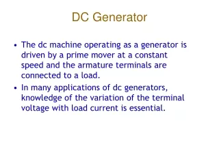
DC Generator. Generator Principle An electrical generator is a machine, which converts mechanical energy (or power) into electrical energy (or power).

DC Generator
E N D
Presentation Transcript
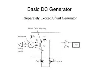
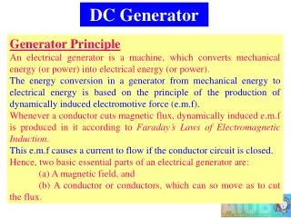
DC Generator Generator Principle An electrical generator is a machine, which converts mechanical energy (or power) into electrical energy (or power). The energy conversion in a generator from mechanical energy to electrical energy is based on the principle of the production of dynamically induced electromotive force (e.m.f). Whenever a conductor cuts magnetic flux, dynamically induced e.m.f is produced in it according to Faraday’s Laws of Electromagnetic Induction. This e.m.f causes a current to flow if the conductor circuit is closed. Hence, two basic essential parts of an electrical generator are: (a) A magnetic field, and (b) A conductor or conductors, which can so move as to cut the flux.
Simple Loop generator Construction: A single-turn rectangular copper coil ABCD, as shown in Fig. 24.1a, rotating about its own axis in a magnetic field provided by either permanent magnets or electromagnets. The two end of the coil are joined to slip-rings ‘a’ and ‘b’ which are insulated from each other and from the central shaft. Two collecting brushes (of carbon or copper) press against the slip-rings. Their function to collect current induced in the coil and to convey it to the external load resistance R. The rotating coil may be called “armature” and the magnets as “field magnets”.
Working Principle The coil sides AB and CD now represent by A and B as shown in Fig.2.9. Imagine the coil to be rotating in clock-wise direction. When the coil sides A and B are at position 1, the plane of the coil is at right angles to line of flux, the flux linked with the coil is maximum but rate of change of flux linkages is minimum. It is so because in this position, the coil sides A and B do not cut or share the flux, rather the slide along them i.e. they move parallel to the lines of flux. Hence there is no induced e.m.f in the coil. As the coil continues rotating further, the rate of change of flux linkages (and hence induced e.m.f in it) increases, till the angle equals 90o.
At position 2, the voltage induced in the coil is at a maximum because the conductors are moving at right angles to the lines of flux. In this position, the coil plane is horizontal i.e. parallel to the lines of flux. As seen, the flux linked with the coil is minimum but rate of change of flux linkages is maximum. Hence maximum e.m.f is induced in the coil when in this position 2. The direction of current in the coil can be obtained in accordance with Feming’s right-hand rule. In the next quarter revolution i.e. from 90o to 180o, the flux linked with the coil gradually increases but the rate of change of flux linkages decreases. Hence, the induced e.m.f decreases gradually, the angles equals 180o (it is reduced to zero value).
The voltage is again zero at position 3, just as it was at position 1. Coil side A is now at the bottom instead of at the top. We find the first half revolution of the coil, no e.m.f is induced in it when in position 1, maximum when in position 2 and no e.m.f when in position 3 in this half revolution the coil sides A and B are moved in downward. In the next half revolution i.e. from 180o to 360o, the variations in the magnitude of e.m.f. are similar to those in the first half revolution.
The e.m.f value is maximum when coil is in position 4 and minimum when in position 5 (or 1). The direction of current is opposite of the current which is found for the first revolution. Due to the direction of motion (upward direction) the current direction is changed in the next half revolution.
Unidirectional Current Generation We find that the current which is obtained from a simple generator reverses its direction after every half revolution. Such a current undergoing periodic reversals is known as alternating current. For making the flow of current unidirectional in the external circuit, the slip-rings are replaced by split-rings (or commutator) as shown in (a). The split-rings are made out of a conducting cylinder which is cut into two halves or segments insulated from each other by a thin sheet of mica or some other insulating material. The ends of the coil are connected through the split-ring to the brushes which lead to the external circuit.
Previous Fig. (a) can simply be drawn as Fig. 2.10. While the coil moves from position 1 to position 2, the brushes remain in contact with the split-ring segments and the current direction remains as indicated although the magnitude decreases. At position 2 the voltage induced in the coil is zero, and the current in the external circuit is also zero. At this instant segment A leaves brush 1 and makes connect with brush 2. Segment B leaves brush 2 and makes contact with brush 1. As the coil moves from position 2 to position 3, segment A makes contact with brush 2 only, while the current increases from zero and leaves brush 2. Of course, during this same period current returns to the coil through brush 1 and segment B.
1 2 Again, when the current in the coil becomes zero, the segment in contact with the brush changes, thereby maintaining a unidirectional current in the external circuit. This follows from the fact that wire 1 is always connected to the coil side under the North Pole, while coil 2 is always connected to the coil side under the South Pole. Even now the current induced in the coil sides is alternating as before. It is only due to the rectifying action of the split-rings (also called commutator) that is becomes unidirectional in the external circuit. Hence, it should be clearly understood that even the armature of DC generator, the induced voltage is alternating.
Practical Generator Fig. 5 shows a cross-section of a typical commercial DC generator, simplified for emphasis of the major portions. The basic principle underlying construction and working of an actual generator which consists of the following essential parts: 1. Magnetic Frame or Yoke, 2. Pole Coils or Field Coils, 3. Pole-Cores and Pole-Shoes, 4. Interpole (Commutating Pole) 5. Compensating Winding 6. Armature or Rotor Shaft 7. Armature Core, 8. Armature Windings or Conductors, 9. Commutator, 10. Brushes and Brush Rigging, and 11. Bearing
Magnetic Frame or Yoke Yokes are made of cast iron or cast steel or rolled steel. The outer frame or yoke serves double purpose: 1. It provides mechanical support for the poles and acts as a protecting cover for the whole machine, and 2. It carries the magnetic flux produced by the poles. Pole Coils or Field Coils To produce the flux line by means of an electromagnetic, a voltage have to be supplied through a coil. A coil consisting of many turns of fine wire is generally wound around the core. This coil is called shunt field. Also around the core may be found a few turns of heavy wire. This is called the series field. These coils produce the magnotomotive force required to yield the necessary flux cut by the rotating conductors.
Pole-Cores and Pole-Shoes The field magnets consist of pole cores and pole shoes. The core of the pole is built up of laminated steel and the shoe of pole is curved to produce a more uniform magnetic field. • The pole shoes serve the following purposes: • . They spread out the flux in the air gap and also, being of larger cross-section, reduce the reluctance of the magnetic path, and • . They support the exciting coils (or field coils)
Interpole The interpole and its winding are mounted on the yoke of the dynamo. These are located in the interpolar region between the main poles and are generally smaller in size. The interpole winding is composed of a few turns of heavy wire. Since it is connected in series with the armature circuit so that its magnotomotive force (mmf) is proportional to the armature current. Compensating Winding Compensating windings are optional. They are connected in the same manner at the interpole windings but are located in axial slots of the field shoes.
Armature Shaft The moving part of the DC generator is called the armature. The armature consists of a shaft upon which all parts are mounted. The armature shaft, which imparts rotation to the armature core, winding, and commutator. Armature Windings or Conductors The armature winding are usually former-wound. These are first wound in the form of flat rectangular coils and are then pulled into their proper shape in a coil puller. The conductors are placed in the armature slots which are lined with tough insulating material.
Armature Core The material surrounding the shaft is laminated sheet steel and is called the armature core. This magnetic material is necessary to provide a path of low reluctance to the line of flux from the poles. The laminations are required to reduce the eddy current due to the change of flux in the core. Each junction point between coils is connected to a commutator. The commutator segments are insulated from each other and the shaft. The segments form a ring around the shaft of the armature. The armature serves the following functions: 1. It provides a low-reluctance path for the flux, 2. It holds the coils, and 3. It produces motion so that the coils can cut the flux.
Commutator The function of commutator is to facilitate collection of current from the armature conductors. It rectifies i.e. converts the alternating current induced in the armature conductors into unidirectional current in the external load circuit. The segments of commutator are insulated from each other by thin layers of mica. The number of segments is equal to the number of armature coils. Each commutator segments is connected to the armature conductor by means of a copper lug or strip (or riser).
Brushes and Brush Rigging The brushes, whose function is to collect current from commutator, are usually made of carbon or graphite and are in the shape of a rectangular block and supported from the stator structure by a rigging. These brushes are housed in brush-holders usually of the box-type variety. The brushes are made to bear down on the commutator by a spring whose tension can be adjusted by changing the position of lever in the notches. A flexible copper pigtail (the current is taken from the brush by means of a flexible copper wire embedded in the brush, called the pigtail) mounted at the top of the brush conveys current from the brushes to the holder.
Bearings The armature is supported at each end by a metal framework called end bells. The end bells contain the bearings in which the armature rotate. One end bell is left open or made with a cover that can be removed to inspect the brushes. The open end bell also aids in the natural cooling of the generator. Because of their reliability, ball-bearings are frequently employed though for heavy duties, roller bearings are preferable.
Rotor of a dc machine Cutaway view of a dc machine. DC machine stator with poles visible.
Armature Windings Coil: One or more turns of wire grouped together and mounted on the drum wound armature in order to cut lines of flux as shown in Fig. 4.1. Coil side: Any side of coil that cuts lines of flux. Winding Element: The side of coil is called a winding element. Obviously, the number of winding elements is twice the number of coils. Conductor (or inductor):The length of a wire lying in the magnetic field and in which an e.m.f. is induced, is called conductor (or inductor). Winding: The complete connection and location of all the coils on the armature. Pitch: A method of measurement. The pitch is measured as the unit of coil sides, slots and commutator segments.
Front End Connection: A wire that connects the end of a coil to a commutator segment. This wire is located at that part of the coil that is nearest the commutator. Back End Connection: A wire or conductor that connects an inductor on one side of the coil to an inductor on the other side of the coil. It is on the end opposite to the commutator. Pole Pitch: It may be variously defined as: (a) The distance between identical points on adjacent poles i.e. the periphery of the armature divided by the number of poles of the generator. (b) It is equal to the number of armature conductors (or armature slots) per pole. Coil Span or Coil Pitch (Ys):It is the distance, measured in terms of armature slots (or armature conductors) between two sides of a coil. It is, in fact, the periphery of the armature spanned by the two sides of the coil.
Full-Pitched: If the coil pitch is equal to pole pitch, then winding is called full-pitched. It means that coil span is 180o electrical degrees. In this case, the coil sides lie under opposite poles, hence the induced e.m.f.s in them are additive. Therefore, maximum e.m.f. is induced in the two coil sides. Fractional Pitched: If the coil span is less than the pole pitch, then the winding is called fractional-pitched. In this case, there is a phase difference between the e.m.f.s in the two sides of the coil. Hence, the total e.m.f. round the coil, which is the vector sum of e.m.f.s in the two sides, is less in this case as compared to that in the full-pitched case. Fractional-pitched windings are purposely used to effect substantial saving in the copper of the end connections and for improving commutation. An armature wound with a fractional pitch is called a chorded winding.
Back Pitch (YB): The number of coil sides or slots spanned by the back end connections. Front Pitch (YF):The number of coil sides or slots spanned by the front end connections. Both front and back pitches for lab and wave winding are shown in Fig. 24.25 and Fig. 24.26. Pitch of Winding (Y) or Resultant Pitch (YR):It is the distance between the beginning of one coil and the beginning of the next coil to which it is connected. Commutator Pitch (YC): The number of commutator segments spanned from one end of a coil to the other end of the same coil. From Fig.24.25 and 24.26 it is clear that for lap winding, YC is the difference of YB and YF whereas for wave winding it is sum of YB and YF.
Single-Layer Winding:It is that winding which one conductor or coil side is placed in each armature slot. Such a winding is not much used. Two-Layer Winding: In this type of winding, there are two conductors or coil sides per slot arranges in two layers. Usually, one side of every coil lies in the upper half of one slot and other side lies in the lower of half of some other slot at a distance of approximately one pitch away. The transfer of the coil from one slot to another is usually made in a radial plane by means of a particular bend or twist at the back end. The coil sides lying at the upper half of the slots are numbered odd i.e. 1, 3, 5, 7, etc. while those at lower half are numbered even i.e. 2, 4, 6, 8, etc.
Degree of Reentrancy of an Armature Winding A winding said to be singly re-entrant if on tracing through it once, all armature conductors are included on returning to the staring point. It is doubly reentrant if only half the conductors are included in tracing through the winding once and so on. Multiplex Winding If there is only one set of closed winding, it is called simplex winding. If there are two such windings on the same armature, it is called duplex winding and so on. The multiplicity affects a number of parallel paths in the armature. For a give armature slots and coils, as the multiplicity increases, the number of parallel paths in the armature increases thereby increasing the current rating but decreasing the voltage rating.
Lap and Wave Windings Two types of end connections of windings are employed, namely, the lap-wound and wave-wound connections as shown in Fig. 24.25 and 24.26. Each winding can be arranged progressively or retrogressively and connected in simplex, duplex and triplex. The following rules, however, applying to both types of the winding: (a) The front pitch and back pitch are each approximately equal to the pole-pitch i.e. windings should be full pitched. This results in increased e.m.f. round the coils. For special purposes fractional pitched windings are deliberately used. (b) Both pitches should be odd; otherwise it would be difficult to place the coils properly on the armature. (c) The number of commutator segments is equal to the number of slots or coils (or half the number of conductors) because the front ends of the conductors are joined to the segments in pairs. (d) The winding must close upon itself.
Uses of Lap and Wave Winding The number of parallel path of wave winding does not depend on the number of pole but the number of parallel path of lap winding depends on number of pole. Each of the two parallel paths of wave winding contains conductor lying under all the poles whereas in lap winding, each of the parallel paths contains conductors which lies under one pair of poles. So, for a given number of poles and armature conductors, the wave winding gives more e.m.f. than the lap winding. Conversely, for the same e.m.f. lap winding would require large number of conductors which will result in higher winding cost and less efficient utilization of space in the armature slots. Hence, means wave winding is suitable for comparatively low-current but high voltage generators because it gives smaller parallel paths. And, lap winding is suitable for comparatively low-voltage but high current generators because it gives more parallel paths. In wave winding, equalizing connections are not necessary whereas in a lap winding they definitely are. Any inequality of pole fluxes affects two paths equally; hence their induced e.m.f.s are equal. In lap-wound armatures, unequal voltages are produced which set up a circulating current that produces sparking at brushes.