DC-DC Converter
DC-DC Converter. Aashiv Shah Peng Xu Sheesh Nanda. Why DC-DC Converter?. Parts of Maharashtra, India have unreliable power supply Pedal Power used to charge batteries and run gadgets Batteries are 12 Volts and cannot be used to run radios, lamps etc as they need 3V/6 V


DC-DC Converter
E N D
Presentation Transcript
DC-DC Converter Aashiv Shah Peng Xu Sheesh Nanda
Why DC-DC Converter? • Parts of Maharashtra, India have unreliable power supply • Pedal Power used to charge batteries and run gadgets • Batteries are 12 Volts and cannot be used to run radios, lamps etc as they need 3V/6 V • Our design, which converts 12V to 3V/6V will be used to overcome this problem
OVERVIEW • Open Loop Used a potentiometer to verify working of circuit without feedback • Closed Loop Added feedback to the circuit and checked working of circuit for outputs of 6V/3V • PCB Implementation Implemented our circuit using Easytrax
Component used in circuit • TL494 • IR2117 • MTP50N60V • 1N5820-T
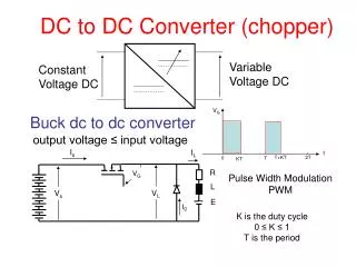
TL 494 • Pulse Width Modulation Chip • Used to set Duty Ratio Duty Ratio is set to 0.25 to obtain an output of 3V and 0.5 to obtain an output of 6V
IR2117 • High Side Gate Drive • Output of TL 494 not large enough to drive the transistor. • IR 2117 increases the output of the TL 494 so that it can be used to drive the transistor
Selection of Diode and Transistor • Diode requires blocking voltage of 12V, forward current of 0.5A and fast switching • Selected 1N5820 Schottky with following parameters Blocking Voltage of 20V Forward current of 3A • Transistor requires same parameters as diode MTP50N06V with blocking voltage of 60V and forward current of 42A used
TL494 • 1IN+,1IN- input to amplifier • CTTiming Capacitor • RT Timing Resistor • REF Reference Voltage • C1 Output
TESTING OF TL494 • Voltage waveform across CT (3V peak to peak) (Timing Capacitor) • Voltage across C1 • PWM comparator combines the saw-tooth waveform from the timing capacitor and DC voltage from potentiometer to give square waveform • Obtain duty ratio from on-time of TL494
OPEN LOOP CIRCUIT • Connect the REF and FEEDBACK with the potentiometer • Manually changed the duty ratio by using the potentiometer as a voltage divider • Used to test the circuit to get 3V/6V output
Close Loop Circuit • Compare the value of the output with the reference value from the TL494 use the error amplifier in TL494 • The gain of the amplifier is 1/RC • Through the testing found out R=10KOhms, C=2.2microF • It will provide the duty ratio we need
TESTING OF CIRCUIT • Input 12 V Multimeter Reading • Output 3.12 V (when switch is turned to one side) • Current drawn =0.13 A • Output 5.7V (when switch is turned to other side) Oscilloscope Reading • Output 3.2V (when switch is turned to one side) • Current drawn = 0.13 A • Output 6.25 V (when switch is turned to other side)
CIRCUIT EFFICIENCY • Case 1: Load resistance = 56 ohms Vout = 6V Vin = 12V Iin = 0.1A Pin = 1.2W Pout = Vout^2/R = 6^2/56 = 0.642W Efficiency = Pout/Pin *100 = 54% • Case 2: Load resistance = 40 ohms Vout = 3.1V Vin =12V Iin = 0.1A Pin=1.2W Pout = 3.1^2/40 = 0.171W Efficiency = 15% • Case 3 : Load resistance = 56 ohms Vout = 6.23V Vin = 12V Iin=0.139A Pin=1.66W Pout=6.23^2/56 = 0.97W Efficiency = 60% • Case 4: Load resistance = 40 ohms Vout=3.06V Vin = 12V Iin=0.106A Pin=1.2W Pout=3.06^2/40 = 0.23W Efficiency = 20% • Low Efficiency due to low cost components used and low level of power used so small fluctuations cause large drop in efficiency
CIRCUIT NOISE • Noise for output of 3.12 V Peak-to-peak voltage of noise= 510 mV Frequency of noise = 35 MHz • Noise for output of 5.7V Peak-to-peak voltage of noise = 531.3mV Frequency of noise = 32 MHz
CAPACITIVE LOW-PASS FILTER • Capacitor’s impedance decreases with increasing frequency • The low impedance in parallel with load resistance tends to short out high frequency • Generally preferred over inductive filters as capacitors are much more predictable in their behavior than inductors
SOLUTION • Increase load capacitance to 470 microfarad (at 6.17V) Peak-to-peak ripple voltage changes to 319 mV • Increase load capacitance to 1000 microfarad Peak-to-peak ripple voltage changes to 134 mV • Finally increase load capacitance to 1500 microfarad Peak-to-peak ripple voltage changes to 98mV • Concept is same as capacitive low-pass filter where we connect a capacitor parallel to the load capacitance which in effect is same as increasing the load capacitance
COMPARISON OF NOISE • Noise at 6.1V for load capacitance = 47 microfarad • Noise at 6.1V for load capacitance = 1500 microfarad
SUCCESSES • Got our open loop circuit working for the demo • Got closed loop working • PCB Implementation • Eliminated AC ripple in DC output • Simple and cost-efficient circuit
RECOMMENDATIONS • Use a current fuse of 0.5 A Sets the maximum current limit to 0.5A according to our specifications Prevents damage to the circuit components from high current Increases reliability of our circuit • Better feedback circuit Output voltage will be less responsive to changes in input voltage More robustness • Better low-pass filter More protection against noise Output is DC 3V/6V according to specifications and fluctuates less
SPECIAL THANKS • Chad Carlson : for help in debugging • Joe Mossoba : for help in the design of the circuit • Jim Wehmer : Printed Circuit Board Implementation (parts shop) • Scott McDonald : providing components from the parts shop (parts shop)