Download

1 / 35
450 likes | 1.14k Vues
DC−DC Buck Converter. DC -DC switch m ode con ver te r s. B as ic D C-DC c onverters. Applications D C - motor dr i v es S M PS. Ste p-down c onverter Ste p-up c onverter. Der ive d c irc uits Ste p-down/step-up c onverter (fly b ack) ( Ć uk-converter) F ull-bridge c onverter.

E N D
Basic DC-DCconverters • Applications • DC-motordrives • SMPS • Step-downconverter • Step-upconverter • Derivedcircuits • Step-down/step-upconverter(flyback) • (Ćuk-converter) • Full-bridgeconverter
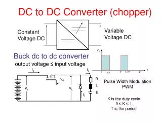
Objective – to efficiently reduce DC voltage The DC equivalent of an AC transformer Iin Iout DC−DC Buck Converter + Vin − + Vout − Lossless objective: Pin = Pout, which means that VinIin = VoutIout and
R1 + Vin − + Vout − R2 Inefficient DC−DC converter The load If Vin = 15V, and Vout = 5V, efficiency η is only 0.33 Unacceptable except in very low power applications
voltage Switch closed Switch open + 15Vdc – R 15 0 Switch state, voltage Closed, 15Vdc Open, 0Vdc DT T A lossless conversion of 15Vdc to average 5Vdc If the duty cycle D of the switch is 0.33, then the average voltage to the expensive car stereo is 15 ● 0.33 = 5Vdc. This is lossless conversion, but is it acceptable?
+ 15Vdc – Rstereo C L + 15Vdc – Rstereo C L + 15Vdc – Rstereo C A DC-DC Buck Converter Convert 15Vdc to 5Vdc, cont. Try adding a large C in parallel with the load to control ripple. But if the C has 5Vdc, then when the switch closes, the source current spikes to a huge value and burns out the switch. Try adding an L to prevent the huge current spike. But now, if the L has current when the switch attempts to open, the inductor’s current momentum and resulting Ldi/dt burns out the switch. lossless By adding a “free wheeling” diode, the switch can open and the inductor current can continue to flow. With high-frequency switching, the load voltage ripple can be reduced to a small value.
C’s and L’s operating in periodic steady-state Examine the current passing through a capacitor that is operating in periodic steady state. The governing equation is which leads to Since the capacitor is in periodic steady state, then the voltage at time to is the same as the voltage one period T later, so or The conclusion is that which means that the average current through a capacitor operating in periodic steady state is zero
Now, an inductor Examine the voltage across an inductor that is operating in periodic steady state. The governing equation is which leads to Since the inductor is in periodic steady state, then the voltage at time to is the same as the voltage one period T later, so or The conclusion is that which means that the average voltage across an inductor operating in periodic steady state is zero
KVL and KCL in periodic steady-state Since KVL and KCL apply at any instance, then they must also be valid in averages. Consider KVL, KVL applies in the average sense The same reasoning applies to KCL KCL applies in the average sense
Capacitors and Inductors In capacitors: The voltage cannot change instantaneously Capacitors tend to keep the voltage constant (voltage “inertia”). An ideal capacitor with infinite capacitance acts as a constant voltage source. Thus, a capacitor cannot be connected in parallel with a voltage source or a switch (otherwise KVL would be violated, i.e. there will be a short-circuit) In inductors: The current cannot change instantaneously Inductors tend to keep the current constant (current “inertia”). An ideal inductor with infinite inductance acts as a constant current source. Thus, an inductor cannot be connected in series with a current source or a switch (otherwise KCL would be violated)
Buck converter • Assume large C so that Vout has very low ripple • Since Vout has very low ripple, then assume Iout has very low ripple + v – L i I L out i in + L V V C out in i C – What do we learn from inductor voltage and capacitor current in the average sense? + 0 V – I I out out i in + L V V C out in 0 A –
+ (Vin – Vout) – i I i L out in + L V V C out in (iL –Iout) – Reverse biased, thus the diode is open The input/output equation for DC-DC converters usually comes by examining inductor voltages Switch closed for DT seconds for DT seconds Note – if the switch stays closed, then Vout = Vin
Switch open for (1 − D)T seconds – Vout + i I L out + L V V C out in (iL – Iout) – iL continues to flow, thus the diode is closed. This is the assumption of “continuous conduction” in the inductor which is the normal operating condition. for (1−D)T seconds
Since the average voltage across L is zero The input/output equation becomes From power balance, , so Note – even though iin is not constant (i.e., iin has harmonics), the input power is still simply Vin • Iin because Vin has no harmonics
Examine the inductor current Switch closed, Switch open, From geometry, Iavg = Iout is halfway between Imax and Imin iL Imax Iavg = Iout ΔI Periodic – finishes a period where it started Imin DT (1 − D)T T
ΔI Raise Iout Lower Iout ΔI Effect of raising and lowering Iout while holding Vin, Vout, f, and L constant iL ΔI • ΔI is unchanged • Lowering Iout (and, therefore, Pout ) moves the circuit toward discontinuous operation
Effect of raising and lowering f while holding Vin, Vout, Iout, and L constant iL Lower f Raise f • Slopes of iL are unchanged • Lowering f increases ΔI and moves the circuit toward discontinuous operation
Effect of raising and lowering L while holding Vin, Vout, Iout and f constant iL Lower L Raise L • Lowering L increases ΔI and moves the circuit toward discontinuous operation
RMS of common periodic waveforms, cont. Sawtooth V 0 T
V 0 V 0 V 0 V 0 V 0 V 0 0 -V RMS of common periodic waveforms, cont. Using the power concept, it is easy to reason that the following waveforms would all produce the same average power to a resistor, and thus their rms values are identical and equal to the previous example
the ripple = + the minimum value 0 RMS of common periodic waveforms, cont. Now, consider a useful example, based upon a waveform that is often seen in DC-DC converter currents. Decompose the waveform into its ripple, plus its minimum value.
RMS of common periodic waveforms, cont. Recognize that
Inductor current rating Max impact of ΔI on the rms current occurs at the boundary of continuous/discontinuous conduction, where ΔI =2Iout iL 2Iout Iavg = Iout ΔI 0 Use max
Capacitor current and current rating i I L out L C (iL – Iout) iC = (iL – Iout) Note – raising f or L, which lowers ΔI, reduces the capacitor current Iout 0 ΔI −Iout Max rms current occurs at the boundary of continuous/discontinuous conduction, where ΔI =2Iout Use max
MOSFET and diode currents and current ratings i I L out i in L C (iL – Iout) 2Iout Iout 0 2Iout Iout 0 Use max Take worst case D for each
Worst-case load ripple voltage iC = (iL – Iout) Iout C charging 0 T/2 −Iout During the charging period, the C voltage moves from the min to the max. The area of the triangle shown above gives the peak-to-peak ripple voltage. Raising f or L reduces the load voltage ripple
Voltage ratings i I i L out in C sees Vout + Switch Closed L V V C out in i C – Diode sees Vin MOSFET sees Vin i I L out Switch Open + L V V C out in i C – • Diode and MOSFET, use 2Vin • Capacitor, use 1.5Vout
There is a 3rd state – discontinuous I out MOSFET + L V V C out in I DIODE out – • Occurs for light loads, or low operating frequencies, where the inductor current eventually hits zero during the switch-open state • The diode opens to prevent backward current flow • The small capacitances of the MOSFET and diode, acting in parallel with each other as a net parasitic capacitance, interact with L to produce an oscillation • The output C is in series with the net parasitic capacitance, but C is so large that it can be ignored in the oscillation phenomenon
Onset of the discontinuous state iL 2Iout Iavg = Iout 0 (1 − D)T Then, considering the worst case (i.e., D → 0), use max guarantees continuous conduction use min
Impedance matching Iout = Iin / D Iin DC−DC Buck Converter + Vout = DVin − + Vin − Source Iin + Vin − Equivalent from source perspective So, the buck converter makes the load resistance look larger to the source
Our components 9A 250V 5.66A 200V, 250V 16A, 20A 40V 40V 10A 10A 10A Likely worst-case buck situation Our L. 100µH, 9A Our C. 1500µF, 250V, 5.66A p-p Our D (Diode). 200V, 16A Our M (MOSFET). 250V, 20A BUCK DESIGN
0.033V Our L. 100µH, 9A Our C. 1500µF, 250V, 5.66A p-p Our D (Diode). 200V, 16A Our M (MOSFET). 250V, 20A BUCK DESIGN 10A 1500µF 50kHz
Our L. 100µH, 9A Our C. 1500µF, 250V, 5.66A p-p Our D (Diode). 200V, 16A Our M (MOSFET). 250V, 20A BUCK DESIGN 40V 200µH 2A 50kHz