Download
1 / 45
480 likes | 700 Vues
Explore the workings of thermodynamic devices in Cengel and Boles’ chapters, covering various engines and cycles, from piston and gas turbines to Stirling and Ericsson engines. Learn about internal combustion engines, gas turbines, and more. Discover the basics of power and refrigeration cycles. Follow historical advancements, including the Gas Turbine's evolution from Hero of Alexandria to modern jet propulsion by Whittle and Ohain.

E N D
ENGINES, REFRIGERATORS, AND HEAT PUMPS This lecture highlights aspects in Chapters 9,10,11 of Cengel and Boles. Every thermodynamic device has moving parts. To understand these movements, it is important that you watch some videos on the Internet. I will go through these slides in two 90-minutes lectures. Zhigang Suo, Harvard University
How humans tell each other something? • The thing itself • Pictures • Words • Equations • Language • Books • Movies • The Internet
Thermodynamics =heat + motionToo many devices to classify neatly • Fuel (input):biomass, fossil, solar thermal, geothermal, nuclear, electricity. • Application (output): mobile power plant (transpiration in air, land, sea), stationary power plant (electricity generation), refrigerator, heat pump. Power cycle, refrigeration cycle. • Working fluid: Gas cycle (air), vapor cycle (steam, phase change). • Fluid-solid coupling: piston engine (reciprocating, crankshaft), turbine engine (jet, compressor). • Site of burning: external combustion, internal combustion.
Plan • Internal combustion engines • Gas turbines • Stirling and Ericsson engines • Vapor power cycle • Refrigeration cycle
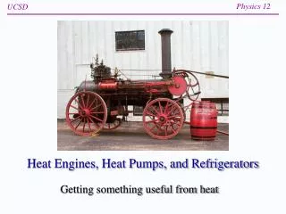
Combustion engine burns to move BOILER STEAM WATER Fayette Internal Combustion Engiine I COMBUSTION CHAMBER PISTON PISTON External combustion engine Internal combustion engine (ICE) • Steam engine • Stirling engine • Ericsson engine • Otto (gasoline) engine • Diesel engine • Gas turbine • Jet propulsion US Navy Training Manual, Basic Machines
Reciprocating engine also known as piston engine, converts linear motion to rotation CYLINDER PISTON CONNECTING ROD CRANKSHAFT US Navy Training Manual, Basic Machines
both valves closed fuel-air mixture entering cylinder air entering fuel-air mixture being compressed exhaust valve closed Fuel discharging from nozzle intake valve open piston moving up piston moving down valve tappet lifting valve cam lobe lifting valve tappet 1 cycle 4 strokes 2 revolutions INTAKE STROKE COMPRESSION STROKE spark igniting mixture both valves closed exhaust valve open intake valve closed Animated engines http://www.animatedengines.com/ piston moving up piston moving down valve tappet lifting valve cam lobe lifting valve tappet US Navy Training Manual, Basic Machines POWER STROKE EXHAUST STROKE
Spark-ignition engine (gasoline engine, petrol engine, Otto engine)
Air-standard assumptions • Model the engine as a closed system, and the working fluid as air (an ideal gas). • The cycle is internally reversible. • Model combustion by addingheat from an external source • Model exhaust by rejecting heat to an external sink
Cold air-standard assumption Model air as an ideal gas of constant specific heat at room temperature(25°C). 2 independent variables to name all states of thermodynamic equilibrium 6 functions of state: PTvush 4 equations of state Gibbs equation
Thermal efficiency of Otto cycle Compression ratio: Conservation of energy: Isentropic processes: Thermal efficiency: wout win
Otto cycle represented in planes of different variables s 3 4 qin qout 2 1 v
Reciprocating engines of two types Spark-ignition engine (Otto, 1876) Compression-ignition engine (Diesel, 1892) https://ccrc.kaust.edu.sa/pages/HCCI.aspx
Compression-ignition engine (Diesel engine) compression ratio: cut-off ratio: Conservation of energy: Isentropic processes Thermal efficiency:
Plan • Internal combustion engines • Gas turbines • Stirling and Ericsson engines • Vapor power cycle • Refrigeration
Gas turbine (Brayton cycle) 4 steady-flow components: isobaric and isentropic P qin 3 2 1 4 qout s
Thermal efficiency of Brayton cycle Definition of pressure ratio: Conservation of energy: Isentropic processes: Thermal efficiency:
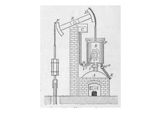
Gas turbine for jet propulsionThousands of years of history Who invented this? Hero of Alexandria Frank Whittle (UK), Hans von Ohain (Germany) (first century AD) (during World War II) http://www.techknow.org.uk/wiki/index.php?title=File:Hero_4.jpg
Gas turbine for jet propulsion 6 steady-flow components Propulsive force: Propulsive power: Propulsive efficiency:
http://www.ae.utexas.edu/~plv955/class/propulsion/Cp_air.GIF
Air as an ideal gas of variablespecific heat See section 7.9 for the use of this table
Plan • Internal combustion engines • Gas turbines • Stirling and Ericsson engines • Vapor power cycle • Refrigeration cycle
Displacer-type Stirling engine https://www.stirlingengine.com/faq/
Stirling engine and regenerator (1816) reversible cycle between two fixed temperatures, having the Carnot efficiency https://people.ok.ubc.ca/jbobowsk/Stirling/how.html
Stirling vs. Carnotfor given limits of volume, pressure, and temperature • On PV plane, the black area represents the Carnot cycle, and shaded areas represent addition work done by the Stirling cycle. • On TS plane, the black area represents the Carnot cycle, and the shaded areas represent additional heat taken in by the Stirling cycle. • The Stirling cycle and the Carnot cycle have the same thermal efficiency. • The Stirling cycle take in more heat and give more work than the Carnot cycle. Walker, Stirling Engine, 1980.
Work out by Stirling cycle Specific work Specific gas constant
Ericsson engine with regenerator (1853) reversible cycle between two fixed temperatures, having the Carnot efficiency
Plan • Internal combustion engines • Gas turbines • Stirling and Ericsson engines • Vapor power cycle • Refrigeration cycle
Brayton Point Power StationSommerset, Massachusetts Mount Hope Bay http://www.clf.org/blog/clean-energy-climate-change/brayton-point-retirement-means-game-coal-new-england/
Nuclear power stationconverts uranium to electricity Animation https://www.awesomestories.com/images/user/be4285df4b.gif http://www.nuclear-power.net/nuclear-power-plant/
Nine Mile Point Nuclear Power Plant, New York Lake Ontario Cooling tower
Why water? Why steam? • Water is cheap. • Water flows! • Water is a liquid at the temperature of heat sink (rivers, lakes,...). • Vaporization changes specific volume greatly: a lot of work at relatively low pressure. https://www.ohio.edu/mechanical/thermo
Rankine cycle 4 steady-flow components: isobaric and isentropic wpump,in = h2 - h1 qboiler,in = h3 - h2 wturbine,out = h3 – h4 qcondenser,out = h4 – h1 P qboiler,in 2 3 wturbine,out wpumo,in 1 4 qcondenser, out s
Carnot cycle is unsuitable as vapor power cycle Issues with the in-dome Carnot cycle Process 1-2 limits the maximum temperature below the critical point (374°C for water) Process 2-3. The turbine cannot handle steam with a high moisture content because of the impingement of liquid droplets on the turbine blades causing erosion and wear. Process 4-1. It is not practical to design a compressor that handles two phases. Issues with supercritical Carnot cycle Process 1-2 requires isothermal heat transfer at variable pressures. Process 4-1 requires isentropic compression to extremely high pressures.
Plan • Internal combustion engines • Gas turbines • Stirling and Ericsson engines • Vapor power cycle • Refrigeration cycle
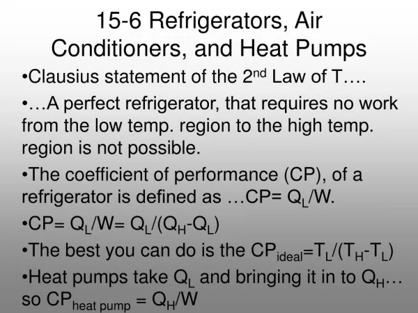
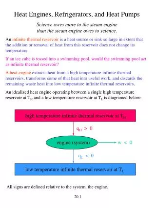
Refrigerator and heat pump 4 steady-flow components
Selecting Refrigerant • Large enthalpy of vaporization • Sufficiently low freezing temperature • Sufficiently high critical temperature • Low condensing pressure • Do no harm: non-toxic, non-corrosive, non-flammable, environmentally-friendly • Low cost • R-717 (Ammonia, NH3) used in industrial and heavy-commercial sectors. Toxic. • R-12 (Freon 12, CCl2F2). Damage ozone layer. Banned. • R-134a (HFC 134a, CH2FCF3) used in domestic refrigerators, as well as automotive air conditioners.
Summary • Engine converts fuel to motion. • Refrigerator and heat pump use work to pump heat from a place of low temperature to a place of high temperature. • Many ideal cycles are internally reversible, but externally irreversible. • Stirling and Ericsson cycles are internally and externally reversible, so they have the same thermal efficiency as the Carnot cycle. • Use ideal-gas model to analyze gas as working fluid. • Use property table to analyze vapor as working fluid. • Model piston engine as a closed system (Otto, Diesel, Stirling, Ericsson). • Model turbine (or compressor) device as steady-flow components in series (Brayton cycle, Rankine cycle, refrigeration cycle).