Download
1 / 19
190 likes | 289 Vues
Get updates on EEX simulations at ANL, including planned experiments to characterize input beam and develop BPM receiver electronics. The simulations include thick lens simulations, collective effects studies, and experiments to verify proper input beam generation. Various tools and components are mentioned for beam characterization and testing. The overall goal is to exchange small normalized emittance for large transverse emittance while achieving specific beam parameters specified in the experiment plan.

E N D
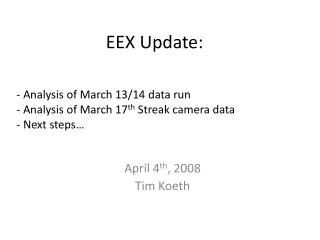
A brief update on EEX at ANL Latest EEX simulations (Planned) Experiment to characterize the input beam Development of BPM receiver electronics
EEX at the AWA AWA photoinjector: Q=100pC; K= 12 MeV; Laser: sx=sy=2.5 mm; sz=1.15 ps; EEX beamline: Q=15 deg; hx = 25 cm; k=4 Photoinjector TQ1,TQ2,TQ3 Gun Linac Emittance Exchanger YAG1 YAG2 GV GV ICT1 TM110 initial ex=10 mm ey=10 mm ez= 3 mm Overall Goal: exchange small eNz for large eNx final ex= 3 mm ey=10 mm ez= 10 mm
1. SIMULATIONS: ImpactT sims of the EEX Thick lens simulations (exact cavity fields and dipole field maps) done, collective effects next. ez= 10 mm ex=10 mm ex=3 mm ez= 3 mm ImpactT Simulations
(Planned) Experiment to characterize the input beam Input to Exchanger ex=10 mm ey=10 mm ez= 3 mm Laser Input Q=100pC sx=sy=2.5 mm sz=1.15 ps 12 MeV 5 MeV TQ1,TQ2,TQ3 Gun Linac YAG1 YAG2 GV GV ICT1 45 MV/m 16 MV/m Goal: Verify we can generate proper input beam
(Planned) Experiment to characterize the input beam (elliptical laser/flat beam) Input to Exchanger ex=26 mm ey=1 mm ez= 10 mm Laser Input Q=100pC sx=2.13 mm sy=21.3 mm sz=1.15 ps 12 MeV 5 MeV TQ1,TQ2,TQ3 Gun Linac YAG1 YAG2 GV GV ICT1 45 MV/m 16 MV/m Goal: Verify we can generate proper input beam
(Planned) Experiment to characterize the input beam • Preparation • Laser room generate and characterize short bunch (done) • elliptical laser profile Use cylindrical telescope to generate profile; Test with relay imaging system; • Transverse Emit • quad scan simulation, imaging system resolution • Scanning slit design, fabricate, install in long stroke actuator, setup ICCD camera (probably unnecessary) • Longitudinal Emit • Linac phase scan simulation (~done), imaging system resolution • Longitudinal Bunch Length • Bolometer based CSR relative measurement
Example with a “real” long. phase space HEAD ez=22.97 mm Longitudinal phase space out of the AWA rf gun just downstream of the booster TAIL
Example with a “real” long. phase space “crest phase” Uncorrelated fractional momentum spread Related to inco-ming chirp (dd/dz)
Example with a “real” long. phase space uncorrelated 9.98 10-4 thin 22.97 10-6 thick -4.0 10-6 4.3 10-3
Example with a “real” long. phase space uncorrelated 9.98 10-4 thin 22.97 10-6 thick -4.0 10-6 4.3 10-3
Rail Spectrometer Diagnostic Rail YAG4 YAG5 Slits BPM ICT2 • ODR/OTR target • Pepper Pot (1nC) • YAG • Slit (100 pC) • Kapton only • Resolution Target 510 394 501 551 356 470 336.9 419 454.5 322.3
LOG AMP S & H SUM Difference Phase Comp