Download

1 / 25
260 likes | 422 Vues
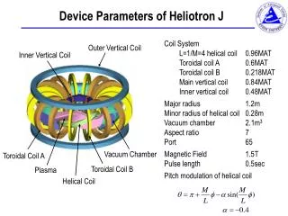
Studies of Improved Confinement in Heliotron J. Presented by MIZUUCHI Tohru for Heliotron J Team. Studies of Improved Confinement in Heliotron J Contents. Heliotron J. IAE, Kyoto University. Introduction Transition to Improved Confinement Configuration Effects

E N D
Studies of Improved Confinement in Heliotron J Presented by MIZUUCHI Tohru for Heliotron J Team
Studies of Improved Confinement in Heliotron J Contents Heliotron J IAE, Kyoto University • Introduction • Transition to Improved Confinement • Configuration Effects • Effects of Heating Scenario • Fueling Control • Summary Due to the time limitation, this talk will focused on “Transition”. For other topics, please contact me or refer the proceeding
i(a)/2p=0.498 i(a)/2p=0.493 i(a)/2p=0.62 i(a)/2p=0.56 The edge magnetic surfaces are strongly modified by the resonant conditions. Vacuum Rotational Transform Ad.Ip STD HFC Sub. Ip The effects of rational surfaces have been studied is not only from the MHD activities but also from the appearance of transport barriers viewpoints.
Magnetic field strength at plasma axis Corner Straight Corner High eb Medium Low Bumpiness ControlB drift can be suppressed with bumpiness control. High eb : Higher mirror ripple Low eb : Mirror field reversal (at axis) Constant parameters : - Rax/<ap> = 1.2 m/0.17 m, Vp ~ 0.7 m3 - Edge rotational transform - Magnetic well in entire region
The Heliotron J experiments have revealed the existence of the spontaneous transition to improved confinement mode. • Observation with fast cameras revealed the existence of filament structure parallel to B in the peripheral plasma turbulence. • Phase image analysis suggests • The CCW poloidal rotation of the filament structure during the L-mode. • During the L-H transition, this rotation speed decreases. • After the transition, it restarts the movement but in CW direction. Ref. Nishino, C09 (Tue) ECH-only plasma
Vp (m3), R (m) Before the transition, Wp strongly depends on i(a)/2p|vac, but it is moderated after the transition. • The transition phenomena were observed almost all (a)/2cases for the input power range in the experiment (ECH+NBI). • Some configurations show a remarkable improvement but the others show a slight improvement. P = PECH ( 0.29 MW) + PNBI ( 0.57 MW)
One robust condition to the transition is the core density.The value of the threshold line-averaged density is not sensitive to the heating method, Pinj level, i(a)/2p|vac. STD configuration PECH (~ 0.29 MW)+PNBI (~ 0.57 MW) • The threshold density is a robust condition of the transition. • The threshold density (lower density limit for the transition) is ~ 1-21019 m-3. • Only for higher values of /2, some exceptional low threshold density cases are observed. MHD activities?
texp/(ftISS04) the “quality of improvement” based on ISS04 seems to depend on the configuration. F. Sano, et al., Nucl. Fusion 45 (2005) 1557. • Iota-windows for high quality H-mode close to the low-mode rationals • All configurations basically have “stellarator shear” (vacuum) hard to get edge flux surfaces on the “right-side” of the rationals. • Difference in the poloidal viscous damping among the configurations can cause the difference in the “quality”? • Still open question. • Bias experiment will give us some information. i(a)/2p|vac
Electrode Bias Exp. in Heliotron J under a Low Field ConditionS. Kitajima, et al., Tohoku Univ.Externally controlled torque could give us a lot of (but NOT sufficient) informationon the viscous damping. Electrode of LaB6 (Hot Cathode) 3 Note: This experiment was performed under a special configuration for 2.45GHz ECH discharge.
Time Evolution of a Biased Discharge Triangular voltage was applied in order to give rise to forward/ back transition. • Rapid increase of IE and ne. • Vs changed from positive to negative. • Drop in the fluctuation level. • Clear hysteresis of IE.
Bias Exp. suggests plasma rotation can modify the edge field topology. Probe array Time traces of ion-saturation currents at divertor probe array during biasing: Increase for some channels, but decrease for other channels. Modification of edge field topology!
texp/(ftISS04) The “quality of improvement” based on ISS04 seems to depend on the configuration. F. Sano, et al., Nucl. Fusion 45 (2005) 1557. • All configurations basically have “stellarator shear” (vacuum) hard to get edge flux surfaces on the “right-side” of the rationals. • Difference in the poloidal viscous damping among the configurations? • But, is that all? • How about the “plasma effects”, especially effects of (non-induction) plasma current. • Experiments suggest the change of the iota and/or the size of the confinement region. i(a)/2p|vac
HINT2 predicts the change of the field topology caused by plasma current: ad. 4kA ad. 2kA ad. 1kA vacuum 0kA sub. 1kA sub. 2kA sub. 4kA b(s) = 0.5·(1-s)2 [%], jp = jp0·(1-s)2 • “Additive” plasma current can modify not only the i/2p-profile but also the “shape” of magnetic surfaces. • Asymmetric effect of plasma current due to the “proximity” to a low-mode rational number.
Experiments suggest the change of the edge field topology during a plasma shot.ECH ( 0.3 MW) + NBI ( 0.7 MW, co-injection) @ STD • The observed non-inductive toroidal plasma current is gradually increases as increase of the stored energy. • In the density range shown in the figure, the observed plasma current is considered to mainly consist of the bootstrap current and the NB induced current. • The profiles of the diverted plasma density at t = 211 and 277 ms. • At 211 ms, the density distribution is consistent with that expected from the vacuum field topology. • At 277 ms, the density peak position shifts inward about 4 cm compared to the position at 211 ms. • The overall trend of the density-peak-position shift seems to be well synchronized with the change of Wp or Ip.
Comparison between Co/CTR NBI-only plasmas - No transition in CTR NBI - • In Co-NBI, the transition were observed, but no transition in CTR-NBI. • Difference in the transition condition between these NBI-only plasmas due to • Deformation of i/2p • Position of rational surface, • Shear, • Shape of LCFS, • Direction of momentum input ?
Dependence of IP at transition on PNB High eb drop (kA) a Dependence of delay time on PNB @ H p I Medium eb delay time (ms) The transition is observed when the plasma current reaches a critical value. • The critical value of the plasma current depends on the configuration;0.7±0.1kA in middle eb1.3±0.2kA in high eb cases. • The observed time delay would be related to the growing-up time of the current. • In high eb case, higher Ip was required. The effects of the plasma current on the field configuration should depend on the vacuum rotational transform. i(a)/2p|vac-scan experiment.
The critical current for NBI-only plasmastrongly depends oni/2pvac. 12/23 12/22 8/17 4/8 8/15 4/7 8/13 (High eb) Ip@transition (kA) Ip (kA) i(a)/2p|vac Close to Rationals? Radial profile of iota • So far, the transition was observed only in Co-NBI (ad. NBCD) plasmas (Pinj < 0.6 MW). • A “critical current” for the transition exists for all config. • Does the change in the rotational transform caused by non-inductive plasma current trigger the transition? Check other heating cases. 0.25 MW < Pinj < 0.6 MW, ne ~ 1.5-21019 m-3
12/23 12/22 8/17 4/8 8/15 4/7 8/13 (High eb) Ip@transition (kA) Ip (kA) i(a)/2p|vac Comparison of the plasma current at the transition for ECH-, NBI-, and ECH+NBI-plasmas ECH-only ECH+NBI NBI-only • Ip,NET itself seems not a key factor? • Need profile data!
Even for the same net current, the deformation of i/2p and the shape of the magnetic surface strongly depend the current profile.- MODEL CALCULATION- <b> ~ 0.32 %, p=p0(1-s2)2 (a) j = j0(1-s)8, Inet = +2.0 kA (b) j = j0(1-s)8, Inet = -2.0 kA (c) j = j0(1-s4)2, Inet = +2.0 kA (d) j = j0(1-s4)2, Inet = -2.0 kA (e) j = j0(60(1-s2)s2-5(1-s2)), Inet = +2.0 kA (f) j = j0(60(1-s2)s2-5(1-s2)), Inet = -2.0 kA
12/23 12/22 8/17 4/8 8/15 4/7 8/13 (High eb) Ip@transition (kA) Ip (kA) i(a)/2p|vac Comparison of the plasma current at the transition for ECH-, NBI-, and ECH+NBI-plasmas ECH-only ECH+NBI NBI-only • Ip,NET itself seems not a key factor? • Need profile data! • Even in low density ECH-only plasma lower than the threshold density, the transition can be observed when the EC driven “additive” current is high enough. • Transition is observed in ECH+NBI plasmas even in the low eb case.
Transition to a better confinement mode was observed in a high ECCD current discharges. • Low-eb, i/2p(a) ~ 0.56, ECH-only with PECH > 0.3 MW • The line-averaged density is much lower than the critical low-density limitobserved in the previous experiments. • No enough experiments, from this point of view, in sub. high ECCD condition.
Summary (1)- Transition to improved confinement - • No transition in CTR-NBI-only plasmaExistence of the “critical current” in Co-NBI-only plasma Change in the rotational transform (and/or its radial profile) caused by plasma current and/or the direction of momentum input can trigger the transition in NBI plasma. • No clear current dependence in ECH-only plasma Difference in the transition condition between NBI-only and ECH-only plasmas. ECH should have some effect on the transition condition in NBI plasma. • In low density (lower than the threshold density) ECH-only plasma, the transition can be observed when the EC driven “additive” current is high enough. Change in the rotational transform (and/or its radial profile) is effective even for ECH-only plasma.
Summary (2)- Transition to improved confinement - for ne > ne,th * Data for different i(a)/2p|vac are necessary. ** Data @ Ip=0 are necessary.
Thank you for your attention! &Thank you All Contributors for NiceCollaborations! F. Sano, K. Nagasaki, H. Okada, T. Minami, S. Kobayashi, S. Yamamoto, S. Ohshima, K. Hanatani, S. Konoshima Institute of Advanced Energy, Kyoto University Y. Nakamura, K. Mukai, S. Kishi, H.Y. Lee, K. Minami, Y. Takabatake Graduate School of Energy Science, Kyoto University T. Mutoh, S. Okamura, Y. Takeiri, K. Y. Watanabe, M. Yokoyama, K. Nagaoka, Y. Yoshimura, Y. Suzuki, H. Takahashi National Institute for Fusion Science N. Nishino Graduate School of Engineering, Hiroshima University S. Murakami Graduate School of Engineering, Kyoto University S. Kitajima, H. Utoh Graduate School of Engineering, Tohoku University Y. Nakashima Plasma Research Center, University of Tsukuba I. Pankratov National Science Center, Kharikov Institute of Physics and Technology, Ukrina Q. Yang, L. Yao, W. Chen Southwestern Institute of Physics, China
No clear threshold power for Phase-I • No clear/simple relation between nth and Pabs. • At the (a)/2 0.493, ECH-only discharges cannot make a transition. configuration effects on the power threshold. • Different power dependence for Phase-I and II? F. Sano, et al., Nucl. Fusion 45 (2005) 1557.