Download

1 / 32
320 likes | 435 Vues
This lecture outlines the fundamental aspects of Wireless Local Area Networks (WLAN). It covers key concepts such as Service Set Identifier (SSID), which serves as the unique network name, and various authentication methods including Open System and Shared Key Authentication. The lecture also explains the processes of WLAN scanning—both passive and active—and the concept of association and disassociation with access points. Additionally, it highlights roaming mechanics, load balancing, and adaptive rate selection for optimal performance in wireless communications.

E N D
Wireless Personal Communications Systems – CSE5807 Lecture: 07 Stephen Giles and Satha K. Sathananthan School of Computer Science and Software Engineering Monash University Australia These slides contain figures from Stallings, and are based on a set developed by Tom Fronckowiak .
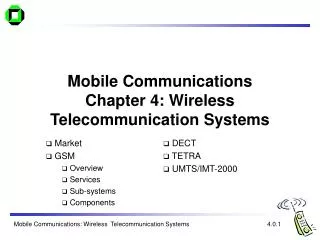
Locating a WLAN • Service Set Identifier (SSID): • Unique, case sensitive, alphanumeric value from 2-32 characters long. • Used as a network name. • Sent in beacons, probe requests, probe responses and other types of frames. • Beacons: • To organize and synchronize wireless communications. • From AP to station in infrastructure mode. • From station to station in ad hoc mode. • Provide functions including • Time synchronization • FH or DS parameters • SSID information • Traffic Indication Map • Supported rates
Locating a WLAN • Scanning: • Passive Scanning • Process of listening for beacons on each channel for a specific period of time. • Continuing process even after association. • Active Scanning • Sending of probe request frame by a wireless station when it seeks a network to join. • The probe request frame contains either a particular network’s SSID or broadcast SSID.
Authentication Request Frame LAN AP Authentication Response Frame Authentication • Wireless client’s identity is verified by the network/access point. • Access Point => Accept/Deny • Authentication Methods: • Open System Authentication • Based on SSID only. • Option of using WEP for only encrypting data. • Shared Key Authentication • Use WEP.
Association Request Frame LAN AP Association Response Frame Association • Allowed to pass data through access point => “Associated”. • Authentication => Association • Wireless client can authenticate more than one access point at a time but can associate only one access point.
AP AP Reassociation Frame Disassociation Frame Roaming • Wireless client determines based on the signal strength. • IEEE802.11 does not define how should be performed. • But some basic building blocks for this process. • Active and passive scanning, reassociation process. • New IEEE802.11f standard for roaming. • Inter Access Point Protocol (IAPP).
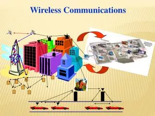
A B B A B A B Load Balancing • Multi-cell structure with co-located access points creating a common coverage area. • Wireless clients automatically associate with the access point that is less loaded and provides the best signal quality.
A A 11 Mbps 2 Mbps Adaptive Rate Selection (ARS) • Speed adjustment with varying distance and interference. • Switched between specified data rates. • Important in planning: • Network throughput • Cell sizes • Power outputs of access points and wireless clients • Security
Power Management • Continuous Aware Mode: • Uses full power and no sleep mode. • Wireless client determines based on the signal strength. • Power Save Polling (PSP): • Wireless client powers down for a very short amount of time. • In BSS, traffic indication map (TIM) is used to notify buffered traffic. • In ad hoc, “Ad hoc traffic indication messages” are used to notify buffered traffic.
LLC Data Link Layer MAC MAC Management PLCP PHY Physical Layer PMD Management IEEE802.11 Physical Layer • Physical Layer Convergence Protocol (PLCP): • Responsible for carrier sensing assessment and forming packets for different physical layers. • Physical Medium Dependent (PMD) protocol: • Defines modulation and coding technique for signaling. • Physical Layer Management: • Decides on channel tuning to different options for each physical layer.
1 or 2 Mbps) PLCP (always 1Mbps) SYNC (80) SFD (16) PLW (12) PSF (4) CRC (16) Whitened MPDU (<4096 Bytes) Preamble Header IEEE802.11 Physical Layer: FHSS MPDU: MAC Protocol Data Unit SYNC: Alternating 0 and 1 SFD: Start of Frame Delimiter – specific pattern of 16 bits (0000110010111101) PLW: Packet Length Width PSF: Packet Signaling Field CRC: Cyclic Redundancy Check – to protect the PLCP bits
1 or 2 Mbps) PLCP (always 1Mbps) SYNC (80) SFD (16) PLW (12) PSF (4) CRC (16) Whitened MPDU (<4096 Bytes) Preamble Header IEEE802.11 Physical Layer: FHSS • FHSS PMD hops over 78 channels of 1 MHz in the center of the 2.44 GHz ISM bands. • Modulation: Gaussian Frequency Shift Keying (GFSK) • 1Mbps – Two levels of GFSK • 2Mbps – Four levels of GFSK • Three patterns of 26 hops => Selection by PHY Management layer. • 0, 3, 6, 9,……75 • 1, 4, 7, 10, …..76 • 2, 5, 8, 11, …..77 • Minimum hop rate 2.5 hops per second. • Maximum transmitted power is 100mW.
1 or 2 Mbps) PLCP (always 1Mbps) SYNC (128) SFD (16) Signal (8) Service (8) Length (16) FCS (8) MPDU Preamble Header IEEE802.11 Physical Layer: DSSS MPDU: MAC Protocol Data Unit SYNC: Alternating 0 and 1 SFD: Start of Frame Delimiter – specific pattern of 16 bits (1111001110100000) Signal: Data rate Service : Reserved for future use Length: Length of MPDU in microsecond FCS: PLCP header coding
1 or 2 Mbps) PLCP (always 1Mbps) SYNC (128) SFD (16) Signal (8) Service (8) Length (16) FCS (8) MPDU Preamble Header IEEE802.11 Physical Layer: DSSS • Barker code of length 11. • Uses non-overlapping pulses at chip rate of 11Mcps occupying 26 MHz. • Modulation: • 1Mbps => DBPSK • 2Mbps => DQPSK • ISM band at 2.4 GHz divided into 11 overlapping channels spaced by 5 MHz. • Maximum transmit power is 100mW.
IEEE802.11b Physical Layer • Defines a new coding, Complementary Code Keying (CCK) to support data rates of 5.5 Mbps and 11Mbps. • 1Mbps => Barker Code and DBPSK • 2Mbps => Barker Code and DQPSK • 5.5Mbps => CCK and DQPSK • 11 Mbps => CCK and DQPSK • Uses the same PLCP as the IEEE802.11 DSSS standard. • Interoperates with IEEE802.11 networks.
IEEE802.11a Physical Layer • Based on OFDM scheme. • Operates at 5 GHz UNII bands. • Eight non-overlapping channels of 20 MHz at the two lower bands of the 5 GHz UNII band. • Each channel is divided into 52 subcarreirs, each approximately 300 kHz. • Data is transmitted in parallel on each subcarrier. • Forward Error Correction (FEC) codes are used to correct errors. • Data rates: 6, 9, 12, 18, 24, 36, 48 and 54 • Modulation: BPSK, QPSK, 16-QAM and 64-QAM
IEEE802.11g Physical Layer • Based on OFDM scheme. • Operates at 2.4 GHz ISM bands. • Backward compatibility with IEEE802.11b. • Switch automatically to CCK/Other modulations. • Data rates: 1, 2, 5.5, 6, 9, 11, 12, 18, 22, 24, 33, 36, 48 and 54 Mbps. • Use optional CCK-OFDM.
Wireless LAN: Deployment • Requirements: • - Facility (Building plan). • - Applications. • - Users. • - End user devices. • - Battery longevity. • - Coverage areas. • - Security. • Design: • - System Architecture. • - Identifying standards. • - Selecting devices. • Installation and Testing.
Wireless LAN: Deployment • RF interference (from other devices). • Interoperability issues (eg.: IEEE 802.11 a & IEEE 802.b). • Security holes. • Application interfaces/requirements. • Unclear requirements.
Wireless LAN: Design • Technical Considerations: • Adequate radio coverage throughout the service area. • Adequate capacity to handle traffic load. • Network performance. • Main design steps: • Selection of AP locations. • Assignment of radio frequencies to APs.
Wireless LAN: Design • Radio propagation is mostly unpredictable. • Design is iterative process. • Steps involved: • Initial selection of AP locations. • Test and redesign. • - Adjusting the AP locations based on signal strength measurements. • Creation of coverage map. • Assignment of frequencies (or channels) to APs. • Signal strength measurements and minimizing co-channel coverage overlap.
WLAN Design: Access Points • Based on measurements. • Layout and construction of buildings determine the coverage area of each AP. • Must avoid coverage gaps. • Space APs as far apart as possible to minimize: • - the cost of equipment and installations. • - the co-channel overlap.
R D WLAN Design: Access Points
R D WLAN Design: Access Points
WLAN Design: Channel Allocations • Once APs are located and their coverage areas are identified, radio channels are assigned to the APs. • Radio channels are assigned in a way that provides the smallest possible co-channel overlap. • In high-density areas: • Multiple radio channels. • Reducing the coverage areas of each APs. • Coverage-oriented design: In low density areas, minimizing the number of APs. • Capacity-oriented design: In high-density areas, assuring adequate capacity to serve all users.
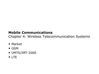
Wireless Metropolitan Area Networks • Defined in IEEE802.16 standard. • Use licensed spectrum in 10 GHz – 66 GHz. • Provide public network service to fee-paying customers. • Use point-to-multipoint architecture with stationary rooftop or tower-mounted antennas. • Provide efficient transport of heterogeneous traffic supporting quality of service (QoS). • Are capable of broadband transmissions.
IEEE 802.16a • Support to mesh network topology. • Line of sight is not required. • Also operates at frequencies between 2 and 11 GHz. • Dynamic Frequency Selection (DFS) to avoid interference with WLAN. • Further MAC and QoS support. • Three radio technologies: • Single carrier modulation format. • OFDM • OFDMA • Centralized and distributed MAC mechanism.
Required Reading • W. Stallings, “Wireless Communications and Networks” Prentice-Hall, 2000. • >> Chapter 13 & 14 Reference • K. Pahlavan and K. Krishnamurthy “Principles of Wireless Networks”, Prentice-Hall, 2002.