Download

1 / 23
230 likes | 377 Vues
Object Removal in Multi-View Photos. Image Rectification. Image Rectification. Transformation process used to project two-or-more images onto a common image plane. Corrects image distortion by transforming the image into a standard coordinate system. 1.

E N D
Object Removal in Multi-View Photos Image Rectification
Image Rectification • Transformation process used to project two-or-more images onto a common image plane. • Corrects image distortion by transforming the image into a standard coordinate system. 1 Figure 1: Example rectification of source images (1) to common image plane (2). 1
Image Rectification To perform a transform... • Cameras are calibrated and provide internal parameters resulting in an essential matrix representingrelationship between the cameras. • We don’t have access to camera’s internal parameters. • What if single camera was used? • The more general case (without camera calibration) is represented by the fundamental matrix. 2
Fundamental Matrix • Algebraic representation of epipolar geometry. • 3×3 matrix which relates corresponding points in stereo images. • 7 degrees of freedom, therefore at least 7 correspondences are required to compute the fundamental matrix. 3
Corresponding Points • Figure out which parts of an image correspond to which parts of another image. • But what is a ‘part’ of an image? • ‘part’ of an image is a Spatial Feature. • Spatial Feature Detection is the process of identifying spatial features in images.
Spatial Feature Detection - Edges • Canny, Prewitt, Sobel, Difference of Gaussians... Figure 2: Example application of Canny Edge Detection 4
Spatial Feature Detection - Corners • Harris, FAST, SUSAN Figure 2: Example application of Harris Corner Detection 5
Feature Description • Simply identifying a feature point is not in itself useful. • consider how one would attempt to match detected feature points between multiple images. • Scale-invariant feature transform (SIFT) offers robust feature description. 6 • Invariant to scale • Invariant to orientation • partially invariant to illumination changes
SIFT • Uses Difference of Gaussians along with multiple smoothing and resampling filters to detect key points (Feature Points with descriptor data) • Key point specifies 2D location, scale, and orientation.
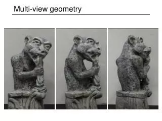
SIFT Figure 3: Sample image for SIFT application
SIFT – Feature Points Figure 4: Detected feature points via SIFT
SIFT – Key Point Figure 5: A SIFT key point in detail.
SIFT - Matching • Matching SIFT key points by identifying nearest neighbour with the minimum Euclidean distance. • Ensures robustness via... • Cluster identification by Hough transform voting. • Model verification by linear least squares.
SIFT - Matching Figure 5: Example of matched SIFT key points. Note its tolerance to image scale and rotation.
SIFT – Suitable for Multi-View? • SIFT fails to accurately match key points between images which vary significantly in perspective. Figure 7 & 8: Comparison of SIFT accuracy with varying perspective angles. Left image is 45 degrees with 152 matches. Right image is 75 degrees with 11 matches.
SIFT – Suitable for Multi-View? • SIFT fails to accurately match key points between images which undergo non-scalable affine transformation or projection. Figure 9: SIFT fails to identify any key point matches between rotated images on a cylinder.
ASIFT • A new framework for fully affine invariant image comparison. • Uses existing SIFT key point descriptors, but matching algorithm has improved.
ASIFT – Improvements over SIFT • Simulated images are compared by a rotation, translation and zoom-invariant algorithm. • (SIFT normalizes translation and rotation and simulates zoom.)
ASIFT – Improvements over SIFT Figure 10: ASIFT (left) identifies 165 matches compared to SIFT’s 11 on surface rotated 75 degrees
ASIFT – Improvements over SIFT Figure 10: ASIFT identifies 381 matches between rotated surfaces.
Image Rectification • Quick Review... • Given multiple images of the same scene from different perspectives... • We have identified & matched feature points using ASIFT. 3. We now have the ability to calculate the fundamental matrix.
References • Oram, Daniel (2001). "Rectification for Any Epipolar Geometry“ • Fusiello, Andrea (2000-03-17). "Epipolar Rectification". http://profs.sci.univr.it/~fusiello/rectif_cvol/rectif_cvol.html. • Richard Hartley and Andrew Zisserman (2004). “Multiple View Geometry in Computer Vision Second Edition” • Ma,Yi. (1996) Basic Image Processing Demos (for EECS20) http://robotics.eecs.berkeley.edu/~sastry/ee20/index.html • Mark Nixon & Alberto Aguado (2002), Feature Extraction & Image Processing, Newnes • Lowe, D. G., “Distinctive Image Features from Scale-Invariant Keypoints”, International Journal of Computer Vision, 60, 2, pp. 91-110, 2004.