Hydrodynamic lubrication
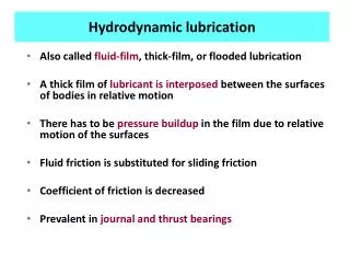
Hydrodynamic lubrication. Also called fluid-film , thick-film, or flooded lubrication A thick film of lubricant is interposed between the surfaces of bodies in relative motion There has to be pressure buildup in the film due to relative motion of the surfaces

Hydrodynamic lubrication
E N D
Presentation Transcript
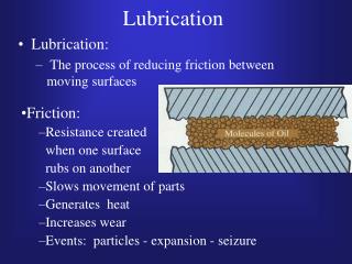
Hydrodynamic lubrication • Also called fluid-film, thick-film, or flooded lubrication • A thick film of lubricant is interposed between the surfaces of bodies in relative motion • There has to be pressure buildup in the film due to relative motion of the surfaces • Fluid friction is substituted for sliding friction • Coefficient of friction is decreased • Prevalent in journal and thrust bearings
Parallel surfaces Direction of motion of top plate Velocity of top plate = u Shear force F Top layer of fluid moves with same velocity as the plate y Velocity profile (same throughout) Velocity of bottom plate = 0 A is area of the plate Lubricant • There is no pressure buildup in the fluid due to relative motion • It remains constant throughout influenced only by the load • As load increases the surfaces are pushed towards each other until they are likely to touch
Hydrodynamic lubrication Lift force Force normal to surface Top surface Top surface Drag force Drag force Direction of movement of oil wedge Oil wedge Oil wedge Bottom surface Bottom surface • Surfaces are inclined to each other thereby compressing the fluid as it flows. • This leads to a pressure buildup that tends to force the surfaces apart • Larger loads can be carried
Hydrodynamic theory- journal bearings Shaft/journal Top surface Oil wedge Oil wedge Bearing Bottom surface Oil wedge forms between shaft/journal and bearing due to them not being concentric
Velocity, pressure distribution Pressure distribution Pmax Top surface Velocity profile at outlet is parabolic convex Oil wedge Velocity profile at inlet is parabolic concave v1 h1 v3 v2 Diverging edge h2 h3 Converging edge Velocity profile at maximum pressue is triangular Bottom surface Volume rate of flow is same throughout the path, therefore as height of film decreases, the velocity has to increase (v3>v2>v1)
Journal bearing- process at startup e = eccentricity Shaft/journal Bearing Stationary journal Instant of starting (tends to climb up the bearing) While running (slips due to loss of traction and settles eccentric to bearing) Because of the eccentricity, the wedge is maintained (lack of concentricity)
Pressure distribution in a journal bearing Shaft/journal SHAFT Bearing Pressure distribution Max. pressure is reached somewhere in between the inlet and outlet (close to outlet)
Tilting pad thrust bearings Number of tilting pads forming wedges Axial direction Wedge formation Ref: http://www.roymech.co.uk/images3/lub_6.gif
Tilting pad thrust bearing Propeller Collar Direction of rotation Bearing plate Pivot Oil wedge Tilting pad Shaft • Back thrust from water to propeller causes axial loading on the shaft • Axial loads are opposed by pressure buildup in the wedge • Gives a damping effect Axial loads from machinery being driven In this case thrust from propeller
Hydrodynamic lubrication- characteristics • Fluid film at the point of minimum thickness decreases in thickness as the load increases • Pressure within the fluid mass increases as the film thickness decreases due to load • Pressure within the fluid mass is greatest at some point approaching minimum clearance and lowest at the point of maximum clearance (due to divergence) • Viscosity increases as pressure increases (more resistance to shear)
Hydrodynamic lubrication- characteristics • Film thickness at the point of minimum clearance increases with the use of more viscous fluids • With same load, the pressure increases as the viscosity of fluid increases • With a given load and fluid, the thickness of the film will increase as speed is increased • Fluid friction increases as the viscosity of the lubricant becomes greater
Hydrodynamic condition- Fluid velocity • Fluid velocity depends on velocity of the journal or rider • Increase in relative velocity tends towards a decrease in eccentricity of journal bearing centers • This is accompanied by greater minimum film thickness
Hydrodynamic condition- Load • Increase in load decreases minimum film thickness • Also increases pressure within the film mass to provide a counteracting force • Pressure acts in all directions, hence it tends to squeeze the oil out of the ends of the bearing • Increase in pressure increases fluid viscosity
Bearing characteristic number Since viscosity, velocity, and load determine the characteristics of a hydrodynamic condition, a bearing characteristic number was developed based on the effects of these on film thickness. • Increase in velocity increases min. film thickness • Increase in viscosity increases min. film thickness • Increase in loaddecreases min. film thickness • Therefore Viscosity x velocity/unit load = a dimensionless number = C C is known as the Bearing Characteristic Number The value of C, to some extent, gives an indication of whether there will be hydrodynamic lubrication or not