Enhancements in CO2 Cooling for BPIX: Upgrading to Four Layers
80 likes | 191 Vues
This document discusses the design goals for upgrading the BPIX cooling system from three to four layers of CO2 cooling. It outlines the power dissipation assumptions based on SLHC luminosity, the operational parameters for CO2 cooling, and calculations for pressure drops across the cooling system. By implementing a cooling system with optimized flow and small diameter pipes, the upgraded design aims to ensure efficient thermal management under maximum loading conditions. Scenarios for pipe layouts demonstrate the feasibility of this approach.

Enhancements in CO2 Cooling for BPIX: Upgrading to Four Layers
E N D
Presentation Transcript
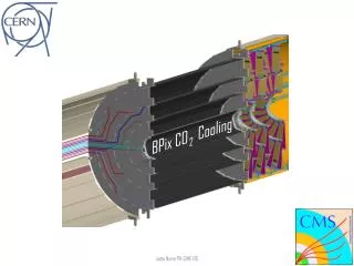
BPIX Cooling with CO2 Assuming 3 or 4 Layers W. Bertl - PSI
Design Goals for BPIX Upgrade 4 Layers instead of 3 Avoid “half” modules Closer to beam pipe (more see in Streuli’s talk) Layer # faces mod/face # pipes L1 16 (16+4) 8 (8) 20 (18) L2 28 (28+4) 8 (8) 32 (30) L3 44 (40+4) 8 (8) 48 (42) L4 64 (-------) 10 (-) 68 (--) Layers placed at R1 = 39 mm (now 44) R2 = 68 mm (73) R3 = 109 mm (104) R4 = 160 mm (--) W. Bertl - PSI
Power Dissipation Assumptions: full SLHC luminosity 1035 cm-2 s-1 max. irradiation of ALL layers (Numbers based on H.C. Kaestli’s calculations) Power dissipation: (only for detector layers, supply tube NOT included) Layer ROC-current ROC-Power Sensor-Power Layer-Power Power/pipe [mA] [mW/pix] [mW/pix] [W] [W] L1 274 174 45 1880 94 L2 127 86 45 1973 62 L3 77 56 45 2404 50 L4 55 43 45 3807 56 W. Bertl - PSI
CO2-Cooling (layers only!) Assumptions: CO2 @ T = - 20 ºC, P = 20 bar pipe inner diameter d = 1.5 mm allow evaporation of 20% (40%) → ΔH = 56 Ws/g (112) CO2 parameters: liquid gas Density: 1.032 0.052 g cm-3 Viscosity: 1.38E-3 1.33E-4 poise Enthalpy: 458 740 J/g (ΔH = 282 J/g) Required: dP/P small for stable operation W. Bertl - PSI
Pressure Drop P pressure l pipe length d pipe diameter density w velocity Re Reynolds number laminar (Re<2320) turbulent (Re<1E5) turbulent (Re<2E6) W. Bertl - PSI
Some Results (@max. load) Two examples: liquid → gas at20% (40%) Scenario 1: all pipes parallel loaded, supply/return at different z (like now) Layer mass flow [g/s] velocity [cm/s] DP [bar] L1 1.67 (0.83) 101 (56) 0.053 (0.017) L2 1.10 (0.55) 67 (37) 0.025 (0.008) L3 0.89 (0.44) 54 (30) 0.017 (0.006) L4 0.99 (0.50) 60 (34) 0.026 (0.009) Scenario 2: 4 pipes serial, supply/return at same z (like FPIX now) L1 6.67 (3.33) 404 (226) 2.46 (0.80) L2 4.40 (2.20) 266 (149) 1.20 (0.39) L3 3.55 (1.77) 215 (120) 0.82 (0.26) L4 3.97 (2.0) 241 (134) 1.23 (0.40) Supply pipes: d=10mm → both scenarios: 2 loops/layer sufficient → 2 spare loops W. Bertl - PSI
Conclusion 2-phase CO2 cooling with detector pipes as small as 1.5mm diameter should work for BPIX even at max. luminosity 1035 cm-2 s-1 4 detector pipes in serial seems to be upper limit of serialization 2 serial pipes look save Supply pipes from balcony to PP0: existing pipes should be ok (20 bar ?) W. Bertl - PSI