PPT on Road Geometrics
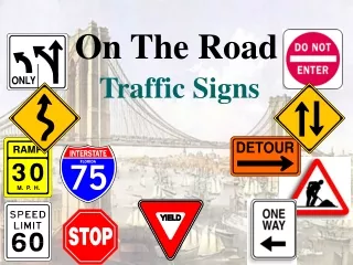
This PPT give information about all the geometrics of road which are important for the design of any road.

PPT on Road Geometrics
E N D
Presentation Transcript
An Expert Lecture on “Geometric Design of Highway” Presented By: Niraj D. Baraiya Lecturer, Civil Engineering Department Acharya Shrimannarayan Polytechnic, Pipri(M), Wardha
Road Geometrics :- • The physical features of a road are known as road geometrics. The physical features have direct connection with the highway users. These are provided according to their geometrical design in order to facilitate safe and economical operation of vehicles. • ☼ Road geometrics include the following elements of highway • Cross sectional elements such as right of way, road margins, formation width, carriage way width, shoulders, side slopes, formation level, camber, gradients etc. • Speed of road vehicles i.e. design speed, average running speed, etc. • Sight distances such as stopping or non passing sight distance, passing or overtaking sight distance, etc. • Curves such as horizontal and vertical curves. • Super elevation etc. • ☼ Geometrics Design of Highways :- • The phase of highway design which deals with the visible elements of different highway is called geometrical design of highways. • A proper geometrical design of a highway is essential before its actual construction to provide speed, safety and comfort to the road users.
☼Right of Way:- The area of land acquired and reserved for construction and development of a road along its alignment is known as right of way or permanent land or Road land. And the width of right of way is called permanent land width or road land width. The area of land outside the right of way which is temporarily acquired for making borrow pits or spoil banks is called temporary land. The width of right of way of a road depends upon the importance of the road and its possible future development. The IRC recommendations for Right of Way are as below:
☼Road Margins:- The portions of land width on either side of the roadway of a road are known as “road margins.” The various elements included in the road margins are parking lane, cycle track, foot path, guard rail, slopes and side drains. Thus road margins are secured and reserved to meet the present and future demands for development of the road.
☼Road way or Formation Width:- The top width of a highway embankment or bottom width of highway cutting excluding the side slopes and side drains is called “Roadway or Formation width.” Roadway width comprises of the width of carriage way including traffic separator, if any, plus the shoulders on either side. The width of roadway standardized by the Indian Road Congress(IRC) are given in table below:
☼Carriage Way:- The portion of roadway constructed for movement of vehicular traffic is called “Carriage Way, Pavement or Crust.” The width of carriage way or pavement depends on the width of traffic lane and number of lanes required. According to IRC specifications, the carriage way width for single lane traffic is 3.75 m. The carriage way widths for different categories of roads as recommended by the IRC are given in table below:
☼Kerbs :- The boundaries between the pavement and shoulders or footpaths are known as “Kerbs.” The kerbs may also be provided between the pavement and traffic Separator or dividing island. Kerbs are generally constructed of cut stone or cement concrete slabs which are chamfered or rounded off.
☼Shoulders:- • The portion of the roadway between the outer edges of the pavement and edges of the top surface of embankment or inner edges of the side drains in cutting are known as Shoulders. • The width of shoulders varies from 0.5 m. to about 4.0 m. according to the nature of the area and type of road. They are always given an outward slope to drain off the rain water quickly towards the sides. The outward slopes to be given to the surface of shoulders as recommended by IRC are given below: • Paved Surfaces :- 1 in 24 to 48 (5% to 2%) • Earth Surfaces :- 1 in 16 to 24 (6% to 5%) • ☼The objects of shoulder:- • They act as components of the Roadway. • They provide lateral stability to the carriage way. • They serve as parking places for vehicles in case of emergency, • They provide space for erecting road signals. • They provide space for animal drawn vehicles, cyclists and pedestrian to retreat when a fast moving vehicle tends to cross or overtake them. • They provide space for accidental repairs to vehicles when they become unserviceable on the road.
☼Side slopes:- The slopes given to the sides of earthwork of a road in embankment or in cutting for its stability are called “Side Slopes.” Side slopes should be so designed as to keep the earthwork stable in embankment or in cutting. Flatter side slopes would make the earthwork uneconomical whereas steeper side slopes would result into erosion and slips. Earthwork embankments of usual height can stand safety with side slope of 1 in 1.5. In cutting, a side slope of 1:1 can serve the purpose. But modern tendency is to provide flatter slopes as they result in safe movements of vehicles and low maintenance cost.
☼Formation level:- The Reduced level of the finished surface of earthwork for a road in embankment or in cutting is known as Formation level. Formation level of a highway should be decided such as to provide economical earthwork in the road project. When the road is to be constructed in embankment, the formation level should be kept above the highest flood level (HFL) in the area. In case of road in cutting, the formation level should be sufficiently above the sub soil water table.
☼Camber:- The convexity provided to the surface of carriage way or the rise given to the centre of carriage way above its edges on straight portion of a road is called “camber or cross fall or cross slope.” Camber is provided on the straight roads by raising the centre of its carriage way with respect to the edges forming a crown at the centre line. It is usually expressed as the percentage of rise given to the crown of the carriage way above its edges. Camber is also expressed as a slope of the line joining the crown with the edges of the carriageway. The amount of Road camber depends on the intensity of Rainfall in the locality and the permeability of the road surfacing material.
The Camber as recommended by the Indian Road Congress (IRC) is given in table below: • ☼Objects of providing camber:- • The camber is usually provided in highway: • To drain off rain water from the surface of carriage towards the sides of a road as quickly as possible. • To regulate the vehicles to their proper lanes. • To improve architectural appearance of the roadway. • To maintain the skid and slip resistance of the pavement by allowing the pavement to get dry soon after the rain.
☼Types of Camber :- • The following types of camber are generally provided to the road Surface. • Composite Camber • Sloped or Straight Camber • Two Straight line Camber • Barrel Camber • (1)Composite Camber :- • It consists of two straight slopes from the edges with a parabolic or circular crown in the centre of carriage way. This type of camber can be easily constructed and maintained.
(2)Sloped or Straight Camber:- It consists of two straight slopes from the edges joining at the centre of carriageway. This type of camber is very simple and can be easily constructed and maintained . (3) Two Straight line Camber:- It consists of two straight lines steeper near the edges and flatter near the crown of carriageway. This type of camber is considered to be the best for Indian Roads because it provide more contact area of the tyres with the road surface than in other type of camber. Thus, it provides less damage to the road surface.
(4)Barrel Camber:- It consists of a continuous curve either elliptical or parabolic. It provides a flat road surface at the middle and steeper towards the edges. On account of steeper edges, this type of camber provides better drainage property. This camber is therefore, preferred by fast moving vehicle and is suggested for urban roads. This, type of camber is difficult to construct and maintain. The barrel camber has more steeper edges which are inconvenient to use. Moreover, the steep edges are erroded quickly.
☼Gradient :- The rate of Rise or Fall provided to the formation of a road along its alignment is called “Grade or Gradient.” It is the longitudinal slope provide to the formation of a road along its alignment. It is expressed as the ration of rise or fall to the horizontal distances or as percentage rise or fall. Thus, if a road ascends or descends one meter for every 20 meters, the gradient is said to be 1 in 20 (1:20) or 5 percent. The gradient may also be expressed in degree of elevation or depression above or below a horizontal plane.
☼Objects of providing Gradient:- • The gradient is usually provided to Road/ Highway: • To connect the terminal stations situated at different level. • To make the earthwork of the road project economical since a perfectly level road involves more cutting and filling. • To provide effective drainage of rain water falling over the road surface, particularly when the pavement is provided with kerbs. • To construct side drains economically with convenient depths below ground level. • To reduce the maintenance cost of road surface. It has been experienced that the maintenance cost is reduced by 15 to 25 percent(%) on a road with slight gradient than that with level surface.
☼Types of Gradient :- • The following are the different types of road gradient. • Ruling Gradient • Limiting Gradient • Exceptional Gradient • Average Gradient • Floating Gradient • Minimum Gradient ☼(1)Ruling Gradient:- The gradient usually adopted while making the alignment of a road is called “Ruling Gradient.” This gradient should never be exceeded in any part of a road in the normal course. This is such a gradient that all vehicles, whether drawn by power or by animals can traverse long lengths of the road without undue consumption of fuel or much fatigue.
☼(2)Limiting Gradient :- The gradient steeper than the ruling which may be used in restricted road lengths where the later is not feasible is called “maximum or limiting gradient.” ☼(3)Exceptional Gradient:- The gradient steeper than the limiting which may be used in short lengths of the road, only in extraordinary situations is called “Exceptional Gradient.” This type of gradient is adopted only in very difficult situations and for short length not exceeding 100 m. at a stretch. In mountainous and steep terrain, successive stretches of exceptional gradients must be separated by a minimum length of 100 m. having gentlier gradient.
The values of Ruling, Maximum(Limiting) and Exceptional gradients as recommended by the IRC are given below in table. (4)Average Gradient:- The total rise or fall between any two points along the alignment of a road divided by the horizontal distance between them is called “ Average Gradient.” (5)Floating Gradient:- The gradient on which a motor vehicle, moving with a constant speed, continues to descend with the same speed without any application of power or brakes is called “Floating Gradient.” (6)Minimum Gradient:- The minimum desirable slope essential for effective drainage of rain water from the road surface is called “Minimum Gradient.”
☼Design Speed:- The maximum safe speed of vehicles assumed for geometrical design of a highway is known as Design Speed. This is the approximately uniform speed that can be maintained by majority of the drivers over the specified category of road. This speed is assumed for correlation of geometrics (physical features) of a road that influence the operation of vehicles. The sight distances, radius of horizontal curve, super elevation, extra widening of pavement, length of horizontal transition curve and the length of summit and valley curve are all dependent on Design speed. The design speed of vehicles on different categories of roads as recommended by the Indian Road Congress (IRC) is given in table below:
☼Sight Distances :- The distance along the centre line of a road at which a driver has visibility of an object, stationary or moving at a specified height above the carriage way is known as Sight Distance. In other words the feasibility to see ahead or the visibility is very important for safe vehicle operation on a highway. • * Factors Affecting the sight distance :- • The safe sight distance depends upon the following factors: • Speed of the Vehicles • Perception time and Brake reaction time • Efficiency of brakes of the vehicle • The friction resistance of the road surface • Height of the drivers eye • Slope of the Road Surface • Eye sight of the driver • Efficient light system during night hours • Weather conditions
☼Type of Sight Distance:- • The various sight distances which are considered for geometrical design of a road can be splitted up into the following types: • Stopping or Non-passing sight distance • Overtaking or passing sight distance • Intermediate sight distance • Lateral sight distance ☼Stopping or non-passing sight Distance:- The clear distance ahead needed by a driver to bring his vehicle to stop before meeting a stationary or moving object on the road is called “Stopping or non-passing sight distance.” In the case of summit curve, minimum stopping sight distance is measured by considering eye sight of driver 1.22 m. above the road surface. Minimum design values of SSD for different speed as per IRC is given in table:
☼Overtaking Sight Distances :- The minimum sight distance needed by a driver on a two way road to enable him to overtake another vehicle ahead with safety against the traffic from opposite direction is called “Overtaking or Passing sight Distance.” The overtaking sight distance or OSD is the distance measured along the centre of the road which a driver with his eye level 1.20 m. above the road surface can see the top of an object 1.20 m. above road surface . Here OSD = total distance traveled by the Vehicle A to overtake the Vehicle B safely without collision with vehicle C coming from opposite direction. OSD = d1 + d2 + d3 OSD = d1 + (b + 2S) + d3
☼Intermediate Sight Distances :- The distance which affords reasonable opportunities to drivers to overtake the vehicle ahead with caution is known as Intermediate Sight Distance. This is taken as twice the safe stopping sight (SSD) distance. ☼Lateral Sight Distances :- The sight distance needed by the driver of a vehicle who sees another vehicle approaching the intersection, reacts and applies brakes to bring his vehicle to dead stop at the intersection without any collision or accident is called “Safe sight distance for entering into an intersection” or “Lateral Sight Distance.”
☼Curves :- The geometrical arcs provided at the change in alignment or gradient of a road are known as Curves. Curves play an important role in the geometrical design of a road. Therefore, they should be so designed as to provide safety and convenience to the traffic. • ☼Necessity of Providing Curves :- • The necessity of providing curves at the change in the alignment or gradient of a road arises due to: • To lay the road according to topography of the area. • To provide access to the particular place. • To avoid costly land. • To avoid excessive cutting or filling. • To make use of the existing bridge. • To make use of the existing bridge. • To keep the driver alert by making change in the direction of Road. • To avoid mental strain caused by the monotony continuous journey along a straight route. • To check the tendency of the driver to increase the speed of his vehicle beyond the safe limits on straight routes.
☼Type of Curves :- Curves on highway have been divided into the following two main classes: (1) Horizontal Curves (2) Vertical Curves. • ☼Horizontal Curves :- • Simple Curve • Compound Curve • Reverse Curve • Transition Curve • ☼Vertical Curves :- • Summit Curve • Valley Curve
☼Super elevation :- The inward transverse inclination provided to the cross section of the carriage way at a horizontal curved portion of a road is called “ Super elevation, Cant or Banking.” • ☼Objects of Providing Super elevation:- • The super elevation is provided on curved portion of Road alignment: • To counteract the effect of centrifugal force acting on the moving vehicle. • To help a fast moving vehicle to negotiate a curved path wihout overturning and skidding. • To ensure safety to the fast moving traffic. • To prevent damaging effect on the road surface due to improper distribution of load. • To reduce the maintenance cost of road on curve portion.
☼Widening of Carriage way on curves :- The provision of extra pavement width at sharp horizontal curves is known as widening of carriage way on curves. An automobile has a rigid wheel base and only the front wheels can be turned when this vehicle takes a turn to negotiate a horizontal curve, the rear wheel do not follow the same path as that of the front wheels. This phenomenon is called “Off Tracking” Thus, the vehicle occupied more width than that it occupies on straight portion of the Road. To compensate this and to provide more visibility on curves, the carriage way width is increased on the entire curved portion of the Road.
It is therefore, necessary to widen the carriageway at sharp horizontal curves to provide for safe passage of vehicles. This widening of carriageway is recommended only when the radius of curve is not above 300 m. As per IRC recommendation the Extra pavement width at Horizontal Curves are given in table below:
***** References ***** • A Text Book of Transportation Engineering – By Shri. N. L. Arora • A Text Book of Highway Engineering – By Khanna & Justo • www.google.com (for Images)