Download
1 / 40
400 likes | 571 Vues
Probabilistic modelling of performance parameters of Carbon Nanotube transistors. Department of Electrical and Computer Engineering. By Yaman Sangar Amitesh Narayan Snehal Mhatre. Overview. Motivation Introduction CMOS v/s CNTFETs CNT Technology - Challenges

E N D
Probabilistic modelling of performance parameters of Carbon Nanotube transistors Department of Electrical and Computer Engineering By Yaman Sangar Amitesh Narayan Snehal Mhatre
Overview • Motivation • Introduction • CMOS v/s CNTFETs • CNT Technology - Challenges • Probabilistic model of faults • Modelling performance parameters: • ION / IOFF tuning ratio • Gate delay • Noise Margin • Conclusion
Overview • Motivation • Introduction • CMOS v/s CNTFETs • CNT Technology – Challenges • Probabilistic model of faults • Modelling performance parameters: • ION / IOFF tuning ratio • Gate delay • Noise Margin • Conclusion
MOTIVATION: Why CNTFET? • Dennard Scaling might not last long • Increased performance by better algorithms? • More parallelism? • Alternatives to CMOS - FinFETs, Ge-nanowire FET, Si-nanowire FET, wrap-around gate MOS, graphene ribbon FET • What about an inherently faster and less power consuming device? • Yay CNTFET – faster with low power
Overview • Motivation • Introduction • CMOS v/s CNTFETs • CNT Technology – Challenges • Probabilistic model of faults • Modelling performance parameters: • ION / IOFF tuning ratio • Gate delay • Noise Margin • Conclusion
CNT is a tubular form of carbon with diameter as small as 1nm • CNT is configurationally equivalent to a 2-D graphene sheet rolled into a tube. Carbon Nanotubes
Single Walled CNT (SWNT) • Double Walled CNT (DWNT) • Multiple Walled CNT (MWNT) • Depending on Chiral angle: • Semiconducting CNT (s-CNT) • Metallic CNT (m-CNT) Types of CNTs
Properties of CNTs • Strong and very flexible molecular material • Electrical conductivity is 6 times that of copper • High current carrying capacity • Thermal conductivity is 15 times more than copper • Toxicity?
CNTFET • How CNTs conduct? • Gate used to electrostatically induce carriers into tube • Ballistic Transport
Overview • Motivation • Introduction • CMOS v/s CNTFETs • CNT Technology – Challenges • Probabilistic model of faults • Modelling performance parameters: • ION / IOFF tuning ratio • Gate delay • Noise Margin • Conclusion
Simulation based Comparison between CMOS and CNT technology Better delay
Simulation based Comparison between CMOS and CNT technology Better delay At lower power!
Overview • Motivation • Introduction • CMOS v/s CNTFETs • CNT Technology – Challenges • Probabilistic model of faults • Modelling performance parameters: • ION / IOFF tuning ratio • Gate delay • Noise Margin • Conclusion
Major CNT specific variations CNT density variation Metallic CNT induced count variation CNT diameter variation CNT misalignment CNT doping variation • Unavoidable process variations • Performance parameters affected Challenges with CNT technology
CNT diameter variation CNT density variation • Current variation • Threshold voltage variation
CNT doping variation CNT Misalignment • Changes effective CNT length • Short between CNTs • Incorrect logic functionality • Reduction in drive current • May not lead to unipolar behavior
Metallic CNT induced count variation m-CNT m-CNT Current s-CNT s-CNT • Excessive leakage current • Increases power consumption • Changes gate delay • Inferior noise performance • Defective functionality Vgs
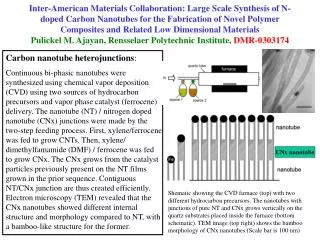
Removal of m-CNTFETs • VMR Technique : A special layout called VMR structure consisting of inter-digitated electrodes at minimum metal pitch is fabricated. M-CNT electrical breakdown performed by applying high voltage all at once using VMR. M-CNTs are burnt out and unwanted sections of VMR are later removed. • Using Thermal and Fluidic Process: Preferential thermal desorption of the alkyls from the semiconducting nanotubes and further dissolution of m-CNTs in chloroform. • Chemical Etching: Diameter dependent etching technique which removes all m-CNTs below a cutoff diameter.
Overview • Motivation • Introduction • CMOS v/s CNTFETs • CNT Technology – Challenges • Probabilistic model of faults • Modelling performance parameters: • ION / IOFF tuning ratio • Gate delay • Noise Margin • Conclusion
Probabilistic model of CNT count variation due to m-CNTs Probability of grown CNT count • ps = probability of s-CNT • pm = probability of m-CNT • ps = 1 - pm • Ngs = number of grown s-CNTs • Ngm = number of grown m-CNTs • N = total number of CNTs
Conditional probability after removal techniques • Ns = number of surviving s-CNTs • Nm = number of surving m-CNTs • prs = conditional probability that a CNT is removed given that it is s-CNT • prm = conditional probability that a CNT is removed given that it is m-CNT • qrs= 1 - prs • qrm= 1 -prm
Overview • Motivation • Introduction • CMOS v/s CNTFETs • CNT Technology – Challenges • Probabilistic model of faults • Modelling performance parameters: • ION / IOFF tuning ratio • Gate delay • Noise Margin • Conclusion
ION / IOFF is indicator of transistor leakage • Improper ION / IOFF → slow output transition or low output swing • Target value of ION / IOFF = 104 Effect of CNT count variation on ION / IOFF tuning ratio
Current of a single CNT • ICNT= ps Is+ pmIm • µ(ICNT) = psµ(Is)+ pmµ(Im) • ICNT =drive current of single CNT (type unknown) • Is =drive current of single s-CNT • Im = drive current of single m-CNT • ps = probability of s-CNT • pm = probability of m-CNT
Ns = count of s-CNT Nm = count of m-CNT Is,on = s-CNT current, Vgs = Vds = Vdd Is,off = s-CNT current, Vgs = 0 and Vds = Vdd Im = m-CNT current, Vds = Vdd ION / IOFF ratio of CNTFET
ION / IOFF ratio of CNTFET µ (Ns) = ps (1 - prs) N µ (Nm) = pm(1 - prm) N
Effect of various processing parameters on the ratio µ(ION) / µ(IOFF) • µ(ION) / µ(IOFF) is more sensitive to prm • µ(ION) / µ(IOFF) = 104 for prm > 1 – 10 -4 = 99.99 % for pm = 33.33% 1- prm
Overview • Motivation • Introduction • CMOS v/s CNTFETs • CNT Technology – Challenges • Probabilistic model of faults • Modelling performance parameters: • ION / IOFF tuning ratio • Gate delay • Noise Margin • Conclusion
Plot of v/s = 0.3 N = 10 N = 20 N = 40 N = 30 N = 50
Plot of v/s N 0.9 0.8 0.6 0.4 0.2 N
Overview • Motivation • Introduction • CMOS v/s CNTFETs • CNT Technology – Challenges • Probabilistic model of faults • Modelling performance parameters: • ION / IOFF tuning ratio • Gate delay • Noise Margin • Conclusion
VIL and VIH pFET • Substituting= Vin, , and • = • Differentiating with respect to Vin and substituting -1 nFET
VIL and VIH For CMOS, For CNTFET, NML = VIL - 0 NMH = VDD – VIH
Overview • Motivation • Introduction • CMOS v/s CNTFETs • CNT Technology – Challenges • Probabilistic model of faults • Modelling performance parameters: • ION / IOFF tuning ratio • Gate delay • Noise Margin • Conclusion
CONCLUSION • Modeled count variations and hence device current as a probabilistic function • Studied the affect of these faults on tuning ratio and gate delay • Inferred some design guidelines that could be used to judge the correctness of a process • Mathematically derived noise margin based on current equations – better noise margin than a CMOS