Download
1 / 34
380 likes | 584 Vues
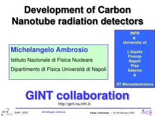
Development of Carbon Nanotube radiation detectors. INFN & University of L’Aquila Firenze Napoli Pisa Salerno & ST Microelectronics. Michelangelo Ambrosio Istituto Nazionale di Fisica Nucleare Dipartimento di Fisica Università di Napoli. GINT collaboration. http://gint.na.infn.it/.

E N D
Development of Carbon Nanotube radiation detectors INFN & University of L’Aquila Firenze Napoli Pisa Salerno & ST Microelectronics Michelangelo Ambrosio Istituto Nazionale di Fisica Nucleare Dipartimento di Fisica Università di Napoli GINT collaboration http://gint.na.infn.it/
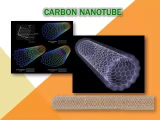
What is a CNT? A graphene sheet can be rolled only one and more than one way, producing single walled and multiwalled carbon nanotubes.
a1≡ a2 ≡ t1 = Carbon Nanotubes: lattice parameters (n,0) zig-zag (n,n) (n,m) chiral c = na1 + ma2 n, m N t1, t2 N Unit cell of CNTs a = t1a1 + t2a2 a0= 2.49 Å t2 =
Carbon Nanotubes (CNTs) Molecular Nanowires (d ~ 1 nm, l ~ 1 m) SWNTs Single Graphene Sheets(d ≈ 0.7 ÷ 3 nm, L≈ mm-range) MWNTs Coaxial graphene sheets (d ≈ 2 ÷ 100 nm, (dout ≈ 20AD, 100CVD nm) L≈ mm-range N |n-m|/3 N Metal Semiconductor Vias Nanocomposites Channel (FETs), Luminescence Ballistic Conduction, e-wave guides, SETs
Physical Properties of Carbon Nanotubes • Superior stiffness and strength to all other materials • Extraordinary electric properties • Reported to be thermally stable in a vacuum up to 2800 oC • Capacity to carry an electric current 1000 times better than copper wires • Twice the thermal conductivity of diamonds • Pressing or stretching nanotubes can change their electrical properties by changing the quantum states of the electrons in the carbon bonds • They are either conducting or semi-conducting depending on the their structure Grace, L. in “Nanotubes for Electronics,” P. G. Collins and P. Avouris, Scientific American, 283(6), pp. 62 ff, Dec, 2000.
Field Emission of CNTs Field Emission from tunneling of electrons from a metal into vacuum I = aEeff2 exp (-b/Eeff) Fowler-Nordheim equation b is a constant, proportional to the work function Eeff is the effective field at the emitter tip a is a constant related to the geometry Emission from well defined energy levels, corresponding to localized states at the tube tip Maximum Current from a single MWNT = 0.2 mA Closed and well-ordered tips are better than opened and disordered tips
e e – – 2r =10 nm – – + + V V h=1.5µm 1µm 10µm Why CNT as emitters? • The aspect ratio h/r produce enormous field amplification factor β • The threshold of field emission is very low d d µTips β =30 V=100 d=1µm CNT β =300 V=100 d=10µm CNT devicesallow themanufacturing of displays with large design rules High beta CNT materials are needed MWCNT electrically connected
CNT energetic levels Semiconductors nanotubes show interesting fluorescence properties in the region of close infrared (from ~ 1 to ~ 15 mm) tied to their electronic characteristics. Nanotubes of type n-m=3p with p entire positive or null are metallic conductors. All the others are semiconductors whose gap is function of the diameter, and are approximated from the function: Egap=2 y0 acc/d where y0=0.1 eV, acc=0.142 nm and d is the diameter. This implies that for the Single Wall CNT the fundamental gap varies from 0.4 to 0.7 eV. Multi Wall CNT instead present a wider range of energy gap.
Metallic Zig-zag Semiconducting Zig-zag Armchair c · K = 2pm m = 1 … q A multiwall carbon nanotube typically consists of a concentric set of nanotubes of both metallic and semiconducting types R. Saito, G. Dresselhaus and M.S. Dresselhaus,Physical Properties of Carbon Nanotubes, Imperial College Press (2003)
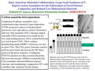
CNT as detectors A layer of Multiwall Carbon Nanotubes covers a wide range of diameters and chirality, offering a device sensitive to a wide range of radiation frequencies. In addition the CNT density is very high, allowing, every in a small area, a great number of tubes sensitive to the radiation. ≈ 108 – 1010 MWCNT / 1 mm2
Photocathods with nanometric resolution Nanotubes have been used as IR detectors. (I.M.Xu: Highly ordered carbon nanotube arrays and IR detection – Infrared Physics and Technology 42 (2001) 485 – 491) (M.E. Itkis: Bolometric Infrared Photoresponse of suspended Single-Walled Carbon Nanotube Film – SCIENCE Vol. 312 (2006) 413 – 416) The realization of large area uncooled detectors for the infrared radiation covers a particular importance for the physics space researches to detect galactic and extragalactic sources The problem: how to collect and amplify the signal generated in individual or “islands” of CNT’s?
Our objective: a CNT_PMT A possible cathode + amplifier layout R I Between the peculiarities of the diamond there is its ability to produce an electron avalanche if invested from an electron of some KeV. That is the energy of the electron incident transforms in an equivalent number of electrons inside the nanodiamond. [I. Ben−Zvi et al. "Secondary emission enhanced photoinjector" Report Brookhaven National Lab Upton NY, C−A/AP\#149]. Vout = I x R
TEM image of MWCNT • Outer diameter: 15 – 25 nm • Inner diameter: 5 – 10 nm • Average # of tubes: 10 – 15
top view Si3N4 5 mm Substrate Si Si3N4 section 7.8 mm 1 mm 2 mm CNTs carpet Au electrodes Sample sketch 500 mm Sample picture
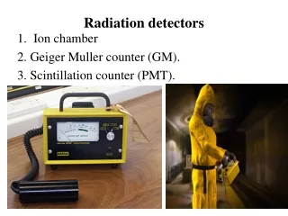
Apparatus layout Fast filter amplifier Ortec 579 Stretcher Ortec 542 ADC Silena MCA PC Bias Supply CNT Device Laser • = 337.1 nm Wmax = 70 mJ/pulse Repetition rate = 10 Hz Pulse shape = 300 ps 50 W Digital oscilloscope
Laser beam spread (FWHMTOT)2 = (FWHMCNT)2 + (FWHMPHD)2 FWHMCNT = √[( 0.027)2 - (0.013)2] = 0.023 nC
Chopper @400Hz lens Monochrom fibre Lamp Photocurrent CNTs 550°C @+20V drain voltage
CNTs growth @ 550°C, sample J1 l = 633 nm
laser position 0 The collected charge is “position sensitive”
Conclusions Carbon nanotubes promise to be very important in the next years as material with unique mechanical, optical and electrical properties The possible application area of CNT is extremely large: idrogen cell, DNA manipulation, medical application, electronics, etc. We can reasonably claim that we are at the beginning of the POST SILICON ERA
Conclusion (2) The GINT collaboration is approaching the problem to build a large area, large frequency range, nano-pixelled, radiation detector with the use of CNT. • First results are very encouraging: • The CNT production has been strongly improved: MWCNT of quite good quality are now availables; • CNTs are analysed with optical methods (FTIR, TEM, SEM, SNOM, Raman) and electronics (I-V plot, field emission) • Analysis on CNT fotoconductivity properties is in progress; • CNT patternization in nanometric scalehas been realized successfully; • CNT modelling is in progress.
We hope to rapidly address the work in the construction of a nano-pixelledlarge area radiation detector with nanometric accuracy
GINT Gruppo INFN per le NanoTecnologie Thank you for your attention