Download
1 / 14
150 likes | 308 Vues
Chelmsford Amateur Radio Society Advanced Course Receivers Part-4 – Receiver Demodulation. Key names when referring to demodulators in receivers:- AM – the envelope detector SSB – the product detector CW – the BFO FM – the ratio detector

E N D
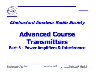
Chelmsford Amateur Radio Society Advanced CourseReceiversPart-4 – Receiver Demodulation
Key names when referring to demodulators in receivers:- AM – the envelope detector SSB – the product detector CW – the BFO FM – the ratio detector Multimode transceivers have a demodulator for each mode and the controls select which one to use This adds complexity - thus the more modern trend to DSP/SDR Terminology – may be referred to as detection or demodulation Receiver Demodulators
D1 Output Modulated RF & Audio Output Envelope Voltage Demodulated RF Input AF Output Time C1 R1 Input Close-in Wider span AM Demodulator • Diode D1 detects the peaks of the IF signal • C1/R1 are a low-pass filter - filtering out the IF, leaving audio • Sometimes called an Envelope Detector
Audio IF Sideband Filter IF Amp Product Detector ~ CIO = Carrier Insertion Oscillator CIO SSB Demodulation • SSB = Single Sideband – without carrier and other sideband • SSB filter selects only the wanted sideband • Product detector mixes to baseband • CIO is at the frequency where carrier would have been • Product detector is a balanced mixer
Amplitude Lower Sideband Upper Sideband Amplitude Upper Sideband Frequency MHz IF Filter Frequency Amplitude Upper Sideband Mixer Frequency MHz USB Demodulation • USB: Signals in Upper Sideband • Unwanted Lower sideband may contain noise and other signals • Mixing with the carrier frequency is product detection • SSB demodulation is essentially mixing to baseband
Amplitude Lower Sideband Upper Sideband Amplitude Lower Sideband Frequency MHz IF Filter Frequency Mixer Amplitude Lower Sideband Frequency MHz LSB Demodulation • LSB: Signals in Lower Sideband • Typically the IF filter is not moved; the local oscillators are offset • When mixed down, the LSB spectrum becomes inverted • SSB demodulation is essentially mixing to baseband
+ Carrier Wave Envelope Detector BFO Beat Note - thus the BFO term CW Demodulation • BFO = Beat Frequency Oscillator • In older times a BFO was an oscillator that “beat” with the CW carrier to make a signal that could be detected as AM…
IF Narrow CW Filter IF Amp Product Detector Audio ~ BFO CW Demodulation … nowadays we use the same product detectors as used for SSB • BFO (Beat Frequency Oscillator) setting is an offset of the CIO • This causes the CW carrier to be mixed down to almost zero frequency so that it sounds like a tone
D1 L2 IF Input C1 Demodulated + Audio Output Ct C3 L3 L1 C2 D2 FM Demodulator • The Ratio Detector • True frequency detector • Relatively unaffected by changes in signal level • Common in valve and transistor receivers, but rarely used today • The transformer is very specialised, nowadays it’s unobtainable
Linear range Output voltage Frequency IF Centre Frequency FM Demodulator Response • Discriminator curve • Output voltage linear with frequency over limited range • Needs correct adjustment otherwise distortion results
FM IC Demodulator • Typical FM 2nd IF integrated circuit used today includes: • Local oscillator • Mixer • IF limiter amp • Quadrature detector • Squelch filter • Squelch trigger • Audio Muting
IF IF Limiter Amp Product Detector Audio Tuned Circuit “Quad Coil” FM Demodulator • In the IC Quadrature detector circuit, a Product Detector acts as a phase comparator • Its output voltage depends on difference in phase between the inputs
1000 800 600 Amplitude (mV) 400 200 300 400 500 600 700 Frequency (kHz) 80 60 40 20 0 Phase (degrees) -20 -40 -60 -80 300 400 500 600 700 Frequency (kHz) FM Demodulator Output • FM demodulators are based on the phase shift of a tuned circuit near resonance • This gives ±45 degree phase shift over 3dB bandwidth • This is known as the“S” curve
Fast Processor Digital to Analogue IF Amp Analogue to Digital Audio IF Spectrum Displays etc DSP demodulators • DSPs (digital signal processors) are fast microprocessors optimised for repetitive maths operations • Signal processing is performed in the digital domain on numeric representations of the signal (samples) • Mathematical algorithms do functions like filtering, mixing, oscillators and amplitude detection • Can also do modulation, voice enhancement, noise reduction