Bending
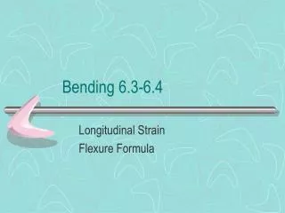
Bending. BADI 1 John Errington MSc. Loaded Beams. When a beam is supported at both ends and loaded it will bend. The amount by which it bends depends on the load, and the way it is distributed the distance between supports the elastic modulus for the material, and

Bending
E N D
Presentation Transcript
Bending BADI 1 John Errington MSc
Loaded Beams • When a beam is supported at both ends and loaded it will bend. • The amount by which it bends depends on • the load, and the way it is distributed • the distance between supports • the elastic modulus for the material, and • the distribution of material in the beam
Loaded beam Here we have a solid square section beam, centrally loaded with a force F and unsupported distance 2x The beam bends into an arc, so the top is shorter than the bottom. This means the top is under compression, and the bottom under tension. The material in the middle (the neutral axis) contributes less to the strength of the beam than the material in the top and bottom quarters of the beam. F 2x For our design we need to know how much the beam will bend, and the maximum stress in the beam to determine whether it will break.
Figure 1. A side view of a simply supported beam (top) bending under a distributed lateral load (bottom). Figure 2.The internal forces and the cross-sectional stress distribution of a beam in bending. Note the position of the neutral axis
Floor loading • The timber floor of a property obviously weighs something. This weight consists of the timber joists, the plasterboard ceiling underneath it, and the floorboards. All of these are known as "the dead load" and the joists themselves must be able to support this dead load without sagging. For a normal property, with chipboard or timber floors and plasterboard ceilings, this dead load is generally taken to be no more than 0.50 kiloNewtons per square metre. (kN/sq.m) • The weight we place upon a floor by way of bathroom suites, beds, wardrobes etc, is known as the "imposed load". It is again accepted that, for normal household requirements, the imposed load will not exceed 1.5kN/sq.m. • The building regulations tables A1 and A2 list the size of joist necessary to support this weight, over a maximum span. Table A2 uses timbers known as "SC4" which are high strength timbers containing very few, if any, knots. They are not common in modern day construction unless specified and we will deal with the more generally used timbers, dealt with in table A1. These timbers are known as SC3 and will have C16 stamped on them.
Steel and concrete • Steel or concrete are often used to support loads, in large buildings and for bridges. • Steel is good under tension and compression • Concrete is excellent under compression, and is lighter than steel, but has low tensile strength
Steel sections RoundsHexagonsSquares FlatsEqual Leg AnglesUnequal Leg Angles Channels "H" Beams "I" Beams Tee Bars Diamond Floor Plate Rectangular Tubing Seamless and Welded Pipe Seamless and Welded Tubing Half Rounds
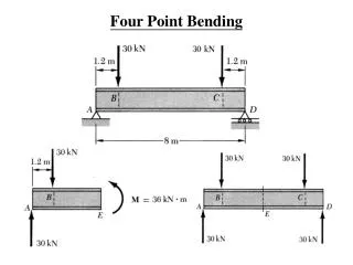
Bending moment for a point load A uniform beam 5m long is supported at its ends and has a load of 6kN at 3m from one end. • What is the reaction in the supports? • What is the bending moment? 3m 6kN 5m
Calculate reaction in supports Taking moments about A we find a CW moment of 3m * 6kN and a CCW moment of -5m * Rb As the system is in equilibrium CW = CCW so 3m * 6kN = -5m * Rb Rb = - 18/5 kN = -3.6kN Also Ra + Rb = - 6kN Ra = - 6kN – (-3.6kN) = -2.4kN Ra = - 2.4kN Rb = - 3.6kN 3m 6kN A B 5m Ra Rb CW = clockwise CCW = counter clockwise
Bending moment for beam with point load To find the bending moment at a point p, x metres from a we take moments about P. To the left of P: Reaction Ra causes a CW moment of 2.4x To the right of P: The load causes a CW moment of 6 * (3-x) Reaction Rb causes a CCW moment of 3.6*(5-x) Total moment = (18 -6x) – (18 -3.6x) = -2.4x i.e. 2.4x CCW So the bending moment for this loaded beam at a distance x from A is Mx = 2.4x. 6kN 3m X m B A p 5m Ra Rb 2.4kN 3.6kN
6kN 3m X m B A p 5m Ra 2.4kN 3.6kN Bending moment and shear force for point load Plotting BM vs x we get this graph, showing BM is a maximum of 7.2 at x =3. We can also plot the shear force acting on the beam. Imagine the beam cut at point p and work out the force acting on the left side of the cut.
Bending moment for a distributed load A beam 3m long is supported at its ends and has a distributed load of 2 tonnes/m. • What is the reaction in the supports? • What is the bending moment? A 2 tonnes/m B 3m
Calculate reaction in supports Distributed load of 2 tonnes / m = 2000kg * 9.81 = 19620N / m The total weight of the load is 19620N * 3m = 58860N By symmetry this is evenly split between the ends, so Ra = Rb = 588600/2 = 29430N A 2 tonnes/m B 3m Ra Rb
Bending moment for beam with distributed load A 19620N/m B To find the bending moment at a point p, x metres from a we take moments about P. To the left of P: Reaction Ra causes a CW moment of 29430x The load causes a CCW moment of 19620 * x *x/2 = 9810 x2 Bending moment Mx= 29430x - 9810 x2 We can show (by plotting, or by differentiating this expression and looking for stationary turning points, then differentiating again) that the maximum bending moment M! for this loaded beam occurs at the mid point, where M! = 29430* 1.5 - 9810 *1.5*1.5 M! = 44145 – 22072 = 22073 Nm p x 3m Rb Ra 29430N 29430N CW = clockwise CCW = counter clockwise
Here you can see that the bending moment is a maximum at the centre, while the shear force is a maximum at the ends. Bending moment and shear force for distributed load
TO BE CONTINUED • Enough for one week. • Next week we will use this information to evaluate how much stress we will get in a loaded beam, and how much it will sag.
Calculate maximum stress in beam and radius of curvature of neutral axis Suppose our beam from the previous example was a steel box girder with dimensions as shown here. • How much would it bend? • Would it break? To answer these questions we need to calculate the radius of curvature , and the maximum stress in the beam. HOW? 0.2m 0.1m Thickness t = 0.02m
/ y = M / I = E / R Where: • is the strain at y metres from the neutral axis M is the bending moment I is the Moment of Inertia for the beam E is Young’s Modulus of elasticity for the material of the beam, and R is the radius of curvature at the neutral axis
Maximum stress The stress is a maximum at the outer faces (top and bottom) of the beam, at a distance D/2 from the neutral axis, where D is the depth of the beam. Using / y = M / I = E / R ! = M! D / 2 I Remember we are using ! to signify a maximum value For our beam M! is 22073 Nm and I= 0.1 * 0.23 /12 – 0.06 *0.163 / 12 I= 6.667*10-5 -2.048*10-5I = 4.619*10-5 m4 (Formula for calculation of I shown later) ! = 22073 * 0.2 / 2 * 4.619*10-5 ! = 47.8 * 106 Pa (1Pa = 1N/m2) Steel has a tensile strength of 1.5*109N/m2 so no problem
Radius of curvature For our steel beam M! is 22073 Nm (calculated) E = 2.1 * 1011 N/m2 (tables) I = 4.619*10-5 m4 calculated) Using / y = M / I = E / R R = I E / M The radius of curvature is given by R = (4.619*10-5 )* (2.1 * 1011) / 22073 R = 439m So how much will our beam sag?
How far does the beam sag? The amount by which the beam sags, x is found using Pythagoras theorem. R2 = a2 + (L/2)2 a2 = R2 - (L/2)2 a = sqrt(R2 - (L/2)2) x = R - sqrt(R2 - (L/2)2) Substituting values for R=439m and L=3m x = 439 - sqrt(4392 - (3/2)2) x = 439 - sqrt(192721 - 2.25) x = 439 – 438.9974 = 2.56 *10-3 m The beam sags by 2.56mm in the centre R a x L/2
Moment of Inertia Defined • The moment of inertia measures the resistance to a change in rotation. • Change in rotation from torque • Moment of inertia I = m * r2 for a point mass • The total moment of inertia I is due to the sum of masses at a distance from the axis of rotation.
Moment of Inertia More importantly for our purposes the moment of inertia describes the way in which the mass of the body is distributed. As we have already seen we can use this parameter to evaluate how a regular isotropic beam will respond to a load.
Extended objects can be treated as a sum of small masses. A straight rod (M) is a set of identical masses Dm. The total moment of inertia is Each mass element contributes The sum becomes an integral distance r to r+Dr length L axis Mass at a Radius
Rigid Body Rotation • The moments of inertia for many shapes can found by integration. • Ring or hollow cylinder: I= MR2 • Solid cylinder: I= (1/2)MR2 • Hollow sphere: I= (2/3)MR2 • Solid sphere: I= (2/5)MR2
The point mass, ring and hollow cylinder all have the same moment of inertia. I= MR2 All the mass is equally far away from the axis. The rod and rectangular plate also have the same moment of inertia. I= (1/3) MR2 The distribution of mass from the axis is the same. M R R M M length R length R axis Point and Ring M
Moment of Inertia of common shapes y is the distance of the NA from the top of the shape. ** indicates raised to power e.g. D**3 = D cubed
Moment of Inertia of a Cross Section b b2 b1 h2 h1 Box Rectangle h A box girder of dimension 0.2m * 0.1m and 0.02m thickness has a csa of 0.012m This amount of material would make a solid bar of 0.12m * 0.1m I(bar) = 1.44 *10-5 m4 I(box) = 6.66 *10-5 – 1.36 *10-5 = 5.3 *10-5 m4
Other shapes • We can calculate the M of I for other shapes just by adding or subtracting, as we did for the box girder. See also next slide. • We can evaluate the M of I at a different point within the shape, using the parallel axis theorem • We can evaluate the M of I about an axis in another plane, using the perpendicular axis theorem
a: Ia =bh**3 / 12 = 1*(1*1*1)/12 = 1/12 Ia = 1/12 b: Ib = I(b outer) - I(a) = (1.414 * 1.414**3) /12 – 1/12 = 4/12 – 1/12 = 3/12 Ib = 3/12 c: Ic = I -I -I +I Ic = { (2*(2**3)) - (1*(2**3)) - (2*(1**3)) + (1*(1**3)) } / 12 Ic = { (2*(8)) - (1*(8)) - (2*(1)) + (1*(1)) } / 12 Ic = { 16 - 8 - 2 + 1} / 12 = 7 / 12 Ic = 7/12 Comparison of moments of inertia for different shapesall having the same cross-sectional area 1m 1m a 1.41m b c 2m
Some objects don’t rotate about an end, but rather about the axis at the center of mass. The moment of inertia depends on the distance between axes. The moment of inertia for a rod about its center of mass: Parallel Axis Theorem h = R/2 M axis
Top view Iy= (1/12) Ma2 b Ix= (1/12) Mb2 M a Side view Iz= (1/12) M(a2 +b2) Perpendicular Axis Theorem For flat objects the rotational moment of inertia of the axes in the plane is related to the moment of inertia perpendicular to the plane.
To Increase the Moment of Inertia • Increase the size: • But as you increase the size, you increase the weight and cost • Use a denser material • But it may not have the properties you need and it will be heavier • Change the cross-sectional shape: • A hollow cross-section is stronger for the amount of material used
We can now work out the stress in a loaded beam, such as a table top or beam bridge. We can find out whether the structure will be strong enough, and how much it will deform under load. Question. A bridge is made of reinforced concrete using pre-stressed reinforcing rods. Should the rods be placed at the top, middle or bottom of the section? WHY? Summary