Bending Moments
200 likes | 504 Vues
Bending Moments. A bending moment exists in a structural element when an external force is applied to the element so that the element bends (or wishes to bend).

Bending Moments
E N D
Presentation Transcript
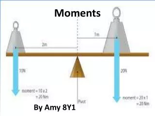
Bending Moments • A bending moment exists in a structural element when an external force is applied to the element so that the element bends (or wishes to bend). • Moments and torques are measured as a force multiplied by a distance so they have as unit newton-meters (N·m) , or foot-pounds force (ft·lbf).
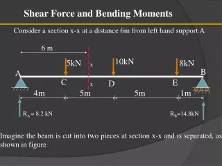
Bending Moments • For example, we have a beam supported at both ends. • A load is placed at the center of the beam. • If we imagine the support at the right side were removed, the beam would want to rotate clockwise about the “A” support side. • The reason why the beam does not bend clockwise about “A” is because there is a counterclockwise moment that is equal to the clockwise moment at the fixed point.
Failure of Structural Components and Bending Moments • The greatest stresses occur on a support beam at the points where the greatest bending moments occur. • Failure in bending will begin to occur when the bending moment is sufficient to induce stresses greater than the yield strength of the material. • Stresses below the yield strength, the material is elastic. Above this point, it is not.
Calculating Bending Moments • Bending moments are calculated using the correct formula for the scenario. • Aspects of the scenario include: • Load distribution • Uniform loading, concentrated loading, multiple loads, unequal loads, etc • Beam Support • Fixed beam • Simple beam • Cantilevered
Formula Values • R = Reaction Load (lbs) • V = Shear Force (lbs) • M = Bending Moment (in.-lbs) • D = Deflection • P = total load (lbs) • x = horizontal distance from reaction point (in.) • l = span length (in.) • I = Moment of Inertia (in 4)
Moment Example • A 10 foot long rectangular steel beam is fixed at both ends. The face of the beam has a dimension of 12” height by a 4” base. It has a concentrated load placed at it’s center point. The following data was collected: • P = total load = 500lbs • x = horizontal distance from reaction point = 60 in. • l = span length = 120 in. • I = Moment of Inertia =
Moment Example • Using the formulas, the maximum positive moment produced occurs at the center of the beam: • The maximum negative moment occurs at the end of the beam by the support.
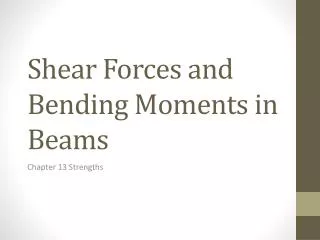
Shear Forces • Shear forces are forces that act parallel along the face of the structure. • The force required to slide the two halves across one another is the shear force.
Shear Force Calculation • R is the reaction force occurring at each support end. • If I have 500 pounds of downward force (P) at the center of the beam, the force is equally split and shared by both end supports (250 lbs of downward force). • Therefore, the reaction load at each bearing point must also be 250 pounds of force. • The shear force is equal to the reaction force.
Deflection • In the previous class, we reviewed deflection. • Deflection is the extent to which a structural support deflects out of horizontal due to load. • Deflection is calculated as the distance below horizontal the member deflects.
Maximum Deflection Calculation • The maximum deflection is this scenario occurs at the center of the beam. • Using the formula in the Shear and Moment Diagram: • Assume that Young’s Modulus for the steel is 30,000,000 psi.
Safety Application • Using a Shear-Bending Moment Diagram, one can determine: • The points where the greatest bending moments occur. • The points where the greatest stresses occur. • The points where the greatest shear forces occur. • By calculating the maximum bending moment, one can determine if, under certain circumstances, the bending moment exceeds the yield stress of the material. • Once can also determine if the shear forces generated exceed the Ultimate Shear Strength of the material. • It is possible that failure of a structural element in shear may occur before failure in bending.