Download
1 / 66
660 likes | 2.18k Vues
Overview. IntroductionDesign EquipmentsHeat ExchangersReactorsCalculations of designHand Calculations (Excel)HYSYS designCost EstimationOperation CostCapital CostCost of ManufacturingResults by CAPCOST. Introduction . ObjectivesDesign of ammonia section in ammonia synthesis plant for a 30 ton/day production of ammoniaEstimate the CostMaterial and energy balance was done in GPI.

E N D
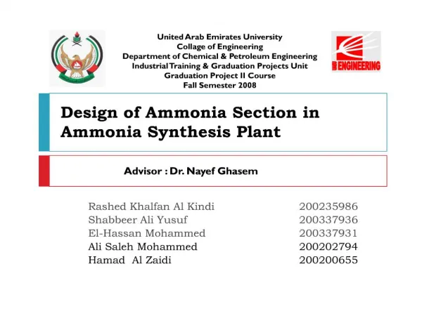
1: Design of Ammonia Section in Ammonia Synthesis Plant Rashed Khalfan Al Kindi 200235986
Shabbeer Ali Yusuf 200337936
El-Hassan Mohammed 200337931
Ali Saleh Mohammed 200202794
Hamad Al Zaidi 200200655
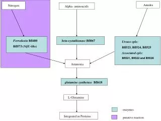
3: Introduction Objectives
Design of ammonia section in ammonia synthesis plant for a 30 ton/day production of ammonia
Estimate the Cost
Material and energy balance was done in GPI
4: Introduction Design of process units theoretically and using HYSYS software
The units designed were reactor and heat exchanger
5: Special concerns related to the process was done
corrective measures
Safety and environmental impact of the project were analyzed
Cost estimation was conducted using CAPCOST software
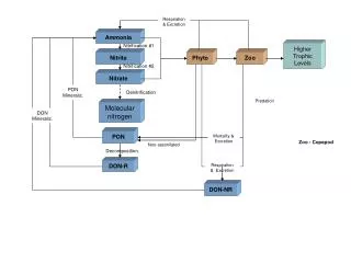
6: Process Flow Diagram
7: Reactor Design
Assumptions
The rate equation from HYSYS
No catalyst, no void fraction
No pressure drop
Change in temperature
8: Derivation The design equation of PFR is
X is the conversion
V is the volume
-rN2 is the rate of reaction of the limiting reagent, nitrogen
FN2o is the input flow rate of the nitrogen
9: Derivation The rate of reaction
kf and kb are the forward and backward rate constants
PN2, PH2, PH3 are the partial pressures of nitrogen, hydrogen and ammonia
10: Derivation The partial pressure of component B
where PBo is the intial partial pressure of component B
b is the stoichiometric coefficient of the component B
?B is the ratio of flow rate of component B to that of flow rate of basis component.
11: Derivation So, for our reaction,
Po is the total input pressure which in this case is
12: Derivation
13: Rate vs. Reactor Volume
14: Derivation Change in temperature through the reactor:
15: Behavior
16: Derivation Change in temperature through the reactor:
17: Derivation
18: Derivation Enter these equations to the polymath software to obtain the volume for 40% conversion
19: Results The volume of the reactor obtained from Polymath is 1.78 m3
Further HYSYS was used to obtain the volume of the reactor by setting the diameter to be 0.75 m. Thus the volume obtained was 0.998m3 for the highest conversion
20: Heat Exchanger Design Importance ? Heat integration
Type of heat exchanger to be designed is countercurrent shell and tube
The most important factor in a heat exchanger design is the heat transfer area (A)
21: Heat Exchanger Design Heat Exchanger design procedures:
Inlet and outlet temperatures are:
Flow rates: mc = mh =0.577 kg/s
22: Heat Exchanger Design 1- Find the physical properties:
2- Calculate the heat transfer rate (q)
q = 148680.4 J/s
23: Heat Exchanger Design 3- also
4- Find (?T)LMTD
(?T)LMTD = 216 oC
5- Find F
24: Heat Exchanger Design R = 0.92 and P = 0.25
? F= 0.98
25: Heat Exchanger Design 6- Assume a value for U = 10 � 50 W/m2.C
7- The heat transfer area (A) is:
A= 14.6 m2
8- choose initial values for L, Do and Di
L = 2.3 m, Do = 0.04 m and Di = 0.036 m
26: Heat Exchanger Design Tube side
9- Calculate the area of one tube
Atube = 0.37 m2
10- Calculate the number of tubes (Nt),
Nt = 40 tubes
11- Find the fluid velocity
uin = 9.14 m/s
27: Heat Exchanger Design 12- Find Reynolds number
Re = 97063.2 ? turbulent flow
13- Find Nusselt number (Nu)
Nu = 314.87
14- Calculate the pressure drop
Np: number of tube passes (2)
?Pt =12.02 kPa
28: To find the tube side friction jf
29: Heat Exchanger Design Shell side
15- Choose the pitch type ? Triangular
16- Find the bundle diameter
Db = 0.867 m
17- Find the shell diameter (Ds), Ds= Db + bundle diametrical clearance
Ds= 0.92 m
18- Calculate the baffle spacing , lB =
lB= 0.184 m
30: Heat Exchanger Design 19- Choose the tube pitch(pt), 1.25*Do, and the baffle cuts, 25%
20- Calculate the cross flow area As,
As = 0.0121 m2
21-Calculate the mass velocity ,
Gs= 47.5 kg / s.m2
22- Calculate the equivalent diameter ,
de = 0.043 m
31: Heat Exchanger Design 23- Calculate the Reynolds number
Re = 17607
24- Calculate the Nusselt number
Nu = 1317.6
25- Calculate the pressure drop
?Ps = 128.7 kPa
32: To find shell side heat transfer factor, jh
33: To find shell side friction factor, jf
34: Heat Exchanger Design Overall heat transfer coefficient
26- Find the local heat transfer coefficient
hin = 1054.5 W/m2.C and ho = 4255.3 W/m2.C
27- Calculate the overall heat transfer coefficient U:
28- Use Goal Seek
Set U = 50 by changing L ? L = 2.35 m
35: Heat Exchanger Design Main Results:
36: Special Concerns Special concerns are out of normal operating conditions.
Specific justification required else don�t use
Normal conditions
Pressure between 1 & 10 bar
Temperatures between 40 �C & 260 �C
37: Concerns in Pressure Pressures up to 10 bars without much additional capital investment
Higher pressures
Thicker walls
More expensive equipment
In vacuum conditions
Large equipment
Special construction techniques
Higher cost
38: Concerns in Temperature At high temperatures common construction materials like carbon steel lose their physical strength drastically
high temperature - economic penalty
more complicated processing equipment
refractory-lined vessels
exotic materials of construction
39: Operating Conditions
40: Reactor High Pressure of 196 bars
Justification
Thermodynamically
Kinetically
41: Kinetic Justification Rate given by:
Concentration becomes by:
Substituting by partial pressure
42: Thermodynamic Justification
@ constant temperature
43: Heat Exchanger Used Heat Integration
If ?Tlm >100�C
Else wastage of usable energy
44: Cost Estimation Profitability of the project
The feasibility of any project proposal should pass the stage of preliminary cost estimation even before any further study can be done on the technical aspects
Type of costs:
- Capital
- Operating
44
45: Capital Cost Cost of the plant ready for start-up
Includes
Design, and other engineering and construction supervision
All items of equipment and their installation
All piping, instrumentation and control systems
Buildings and structures
Auxiliary facilities, such as utilities, land and civil engineering work
45
46: Operating Cost Cost involved in the day to day operation of the plant.
Includes
Direct cost
Raw Materials
Utilities
Operating Labor
Fixed cost
Insurance
Local Taxes
General Expenses
Administration cost
Distribution and selling cost
46
47: Equipments Compressors
Heat Exchangers
Reactors
47
48: Effect of Capacity on purchased cost Cb is the purchased cost of the equipment with base capacity Ab
Ca is the purchased cost of the equipment with required capacity Aa
n is the cost exponent 48
49: 49
50: Effect of time on purchased cost C is purchase cost
I is the cost index
1 refers to base time when the cost is known
2 refers to time when cost is desired 50
51: 51
52: Bare Module cost estimation technique CBM is bare module equipment cost
FBM is bare module cost factor
CPo is the purchase cost for the base condition, i.e. atmospheric pressure and material of construction is carbon steel
52
53: Pressure factor - Fp C1, C2 and C3 are constants for each equipment type 53
54: Material FM 54
55: 55
56: Cost of manufacturing Total direct manufacturing costs
(COM)= CRM + CWT + CUT + 1.33COL +0.3COM + 0.069FCI
CRM is the cost of raw material
CWT is the cost of waste treatment
CUT is the cost of utilities
COL is the cost of operating labor
FCI is the fixed capital investment
56
57: CAPCOST 57
58: Results - Equipment cost
1- Compressor
58
59: Results, cont�.. - Equipment cost
2- Heat Exchanger
59
60: Results, cont�.. - Utility cost 60
61: Results, cont�.. - Material cost 61
62: Results, cont�.. The land cost is estimated to be $ 1,250,000
The operating labor cost is estimated to be $ 700,000 per year
Total cost = $12,844,655
62
63: Results, cont�.. The cost index for 2006 is 478.7
64: Safety and Environmental Impact The exposure limit for ammonia is 25 ppm for 8 hours exposure and 35 ppm for a 15 minutes exposure
Noise
low-noise let-down valves
silencers
Toxic hazard
Explosion are not extremely dangerous
65: Conclusion Volume of the reactor
1.78 m3 (theoretical calculation)
HYSYS value was 0.998 m3
Heat exchanger
shell diameter of 1m and 60 tubes
area of heat transfer 39.48 m2 with a length of 2.35 m.
Total capital cost was $15,548,000
66: Thank you