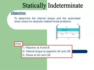
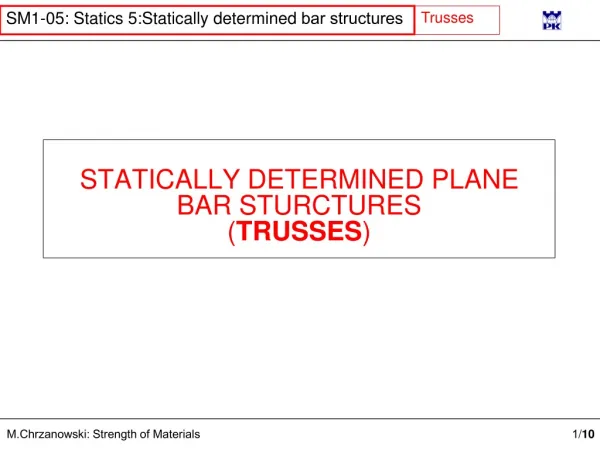
STATICALLY DETERMINED PLANE BAR STURCTURES ( TRUSSES )
STATICALLY DETERMINED PLANE BAR STURCTURES ( TRUSSES ). Formal definition: A f rame is a plane (2D) set of straight bars connected at hinged joints (corners) loaded at hinges by concentrated forces. The simplest truss consist s of three bars connected in hinges.

STATICALLY DETERMINED PLANE BAR STURCTURES ( TRUSSES )
E N D
Presentation Transcript
Formal definition:A frame is a plane (2D) set of straight bars connected at hinged joints (corners) loaded at hinges by concentrated forces The simplest truss consists of three bars connected in hinges. If the only loading will be forces acting at hinges then only cross sectional will be normal forces which can be found considering equilibrium of hinges. Unstable! Frame Truss
Motivation to use trusses is quite different Trusses are aimed to span large areas with a light but durable structures Frame Truss
Strut Tie Under the assumptions:if the structure consists of straight bars connected and loaded at hingesits elements have to bear the normal cross-sectional forces only The structure has to be kinematically stable!
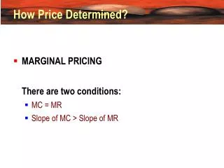
Too many joints, too few bars! w – number of joints p – number of bars Too many bars, too few joints Structure has to be kinematically stable, but can be statically determine or in-determine! ν = 2w – p – 3 Kinematics Statics 2w = number of equations ν > 0 unstable undefined p +3 = number of unknowns ν = 0 determine stable stable ν < 0 In-determine
Examples of kinematically and statically determination ν = 2w – p – 3 Internally and externally determined w = 10, p = 17 ν = 2·10 – 17 – 3 = 0 Kinematically stable Internally determined w = 10, p = 17 Externally indetermined ν = 2·10 – 17 – 4 = -1 Kinematically stable Externally determined w = 10, p =16 Internally indetermined ν = 2·10 – 16 – 3 = 1 Kinematically stable
Y D X = 0 C X = 0 X = 0 X Y = 0 Y = 0 Y = 0 MK = 0 Normal forces in truss elements are to be found from the fundamental axiom that if the whole structure is in equilibrium then any part of it is in equilibrium, too. Such a part of a structure can be obtained by cutting off the truss through three bars not converging in a point (A), or through two bars converging in a node. (B). In the former case we have three equations of equilibrium, in the latter – two. A node can be cut off; then we have two equations of equilibrium (C) , or B any bar with one equation of equilibrium (D). X X = 0 A B
Certain bars are required solely for the purpose of keeping a truss kinematically stable. The cross-sectional forces in these bars vanish; one can call them „0-bars”. A B C A C There are three cases in which we can easily spot „0-bars”: A. When only two bars converge in a node which is free of loading B. When a node connects two bars but the loading acts along of any of these bars C. When unloaded node connects three bars, two of them being co-linear
A B 5 6 9 10 8 7 12 11 13 1 2 3 4 C 5 6 8 9 7 10 12 11 13 1 2 3 4 How does truss work? P=2 All forces in kN 5 6 7 8 9 10 11 12 13 1 2 3 4 R=1 R=1 Bars under tension Bars under compression „0-bars”