Download
1 / 78
950 likes | 1.36k Vues
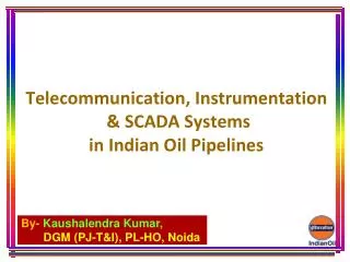
Telecommunication, Instrumentation & SCADA Systems in Indian Oil Pipelines. Indian Oil Pipelines. Indian Oil has a network of over 10000 KM cross- country pipelines throughout the country.

E N D
Telecommunication, Instrumentation & SCADA Systemsin Indian Oil Pipelines
Indian Oil Pipelines • Indian Oil has a network of over 10000 KM cross- country pipelines throughout the country. • Instrumentation Control Systems, SCADA Systems & Telecommunication Systems have a vital role to play in the safe and efficient operations of its cross country pipelines for in time and on-spec delivery of crude oil and petroleum products.
Latest State of the art Instrumentation Reliable SCADA Systems Dependable Communication Systems Failsafe Control Systems Indian Oil Pipelines Cross-country Pipelines Safe, Efficient & Eco-friendly Pipeline Operations Safety of Personnel Safety of Equipment
More Efficient More Reliable Less Interrupted With this, our Pipeline Operations are:- Safer With accurate Measurements Indian Oil Pipelines
Telecommunication, Instrumentation & SCADA Systems PAS SCADA-MCS SCADA-SCC PLC BASED CONTROL SYSTEM FIELD INSTRUMENTATION
Telecommunication Systems For smooth operation of the pipeline, a dedicated communication system with 99.9% (typ.) availability is installed for providing : • An Instantaneous • Reliable & • Continuous exchange of voice & data between pumping/ terminal stations as well as with RCP locations.
Telecommunication Systems Modes of communication in pipelines • H.F. Communication system • V.H.F. Communication system • Public leased circuits on hire • Line of Sight Communication system • Optical fiber Communication system • Satellite Communication system
Telecommunication Systems HF Communication System • A back-up communication system • Very high range up to 1500 km • Low cost • Only simplex or half duplex possible • Requirement of separate frequency for day & night • Now phased out in pipelines
Telecommunication Systems VHF Communication System • Used for communication in a pipeline station / tank farm • Base stations and hand held trans-receivers available • Suitable for short range - typically 2 km to 25 km • Low cost • Cannot be used for inter station communication in pipelines
Telecommunication Systems Line of Sight Communication • Duplex communication • Supports voice, data, fax, computer networking and SCADA systems • Comparable cost with other modes • Obtaining clearances / licenses is time consuming • Very high towers up to 100 M • Maintenance of tower requires specially skilled manpower
Telecommunication Systems Optical Fiber Communication • Works by sending signals down hair thin strands of glass fiber. • Has incredibly high transmission capacity i.e. bandwidth. • Immune to Noise. • Freedom from Cross talk.
Telecommunication Systems Communication Systems in pipelines- • Dual redundant hot standby SDH based systems (up to STM-16, 2.5Gbps backbone links). • Equipped with Network Management System (NMS) at a central location for monitoring, control & configuration of communication equipment installed at different locations. • Optical Fibre Cable Network (12/ 24 Fibre un-armoured cable, ITU-T G.652D, G.655 single mode fibre). • Short haul (40-45 km) & long haul (100-140 km) hops.
Typical Optical Fibre Cable Specifications • Overall Cable diameter : 13 – 14 mm • Wavelengths used: 1310 nm/ 1550 nm • Attenuation @ 1310 nm : 0.36 dB/km • Attenuation @ 1550 nm : 0.23 dB/km
Telecommunication Equipment FCBC 48V Battery Bank Printer PC E P A B X SDH D/I MUX Subscriber Lines Conference Set
E CHARGER ROOM D.G. SET CHARGER EQUIPMENT ROOM ENGINE ROOM BATTERY ROOM A C D B SWITCH FUSE EQPT LOAD DISTRIBUTION BOX BATTERY POWER PLANT RCP Location- Power Set-up
BP SUMP PUMP FS PI LS LT SUMP TANK P&I SCHEMATIC FOR ORIGINATING PUMP STATION WITH TANK FARM, BOOSTER AND ENGINE PUMPING UNITS LS PS PT METER PT TT PROVER TANK DPT DM . . . TM STR TM SEP. FILTER BP DPT S PI L B SD PI PS PT PI PS PT MAINLINE PUMPING UNITS SD PS PS PS PI PI PI PI PI PI PS PS PS PS PS PS PI TO UCP/IFP UCP/IFP UCP/IFP PT NEXT STATION Control Loop
FLOW SWITCHES LEVEL TRANSMITTERS PRESSURE SWITCHES LEVEL SWITCHES PRESSURE TRANSMITTERS FLOW METERS DENSITY METERS TEMP. SWITCHES Our Process Sentinels
Our Process Sentinels • Pressure Indicators • Pressure Switches • Pressure Transmitters • Flow Meters/ Flow Computers • Meter Prover • Temperature Transmitter • Temperature Indicator • Level Switches • Flow Switches • Density Meters • Control Valve • Tank Gauging System • Emergency Shutdown System
Hazardous Area Classification & Protection Standards • Hazardous environments exist in oil refineries, pipeline installations, offshore platforms, chemical plants, mines etc. • Electrical equipment must be suitable for the environment in which they are to be used. • Hazardous areas are classified with respect to the potential danger of explosion and the areas are divided into zones according to the probability of the hazardous atmosphere- Zone 0, Zone 1, Zone 2. • In North America, hazardous areas are classified by classes, divisions, and groups.
Hazardous Area Classification & Protection Standards • Instruments, Equipments in pipeline installations are deployed keeping in view the hazardous area classification. • Protections like Flameproof-Explosion proof, Intrinsic Safety and Ingress Protection are ensured while selection of instruments & equipments. • Each chemical gas or vapour used in industry is classified into a gas group. • Also, to ensure that there is no risk of ignition due to hot surfaces, the equipments/ instruments are classified with regard to the maximum surface temperature of any part of the equipment.
Hazardous Area Classification & Protection Standards • Explosion Protection Methods/ equipment- common types • Flameproof - (Ex d) • Increased Safety - (Ex e) • Pressurisation - (Ex p) • Intrinsically Safe - (Ex i)
Hazardous Area Classification & Protection Standards In case of Intrinsic Safety, the system is designed using safety barriers so that the electrical or thermal energy of a particular instrument loop can never be great enough to cause ignition. Intrinsically Safe Equipment Safety Barrier Control Equipment Room
Control System Station Control Centre • Designed to provide effective & efficient monitoring, safe operation and control of local station and scraper station/ block valves under its control. • Acquires data from local PLC and scraper station/ block valves under its control in real time and transmits the same to MCC. • Configured with dual redundant hot standby computer systems.
Control System • Programmable Logic Controllers (PLCs) are installed at attended stations/ scraper stations for interfacing the field devices. • Remote Terminal Units (RTUs) are installed at unattended block valve stations for interfacing the field devices.
SUPERVISORY, CONTROL AND DATA ACQUISITION SYSTEM SCADA System
SCADA System Petroleum Pipeline SCADA networks • Dedicated SCADA system is installed to provide effective and efficient monitoring and control of the entire pipeline from Master Control Station (MCS). • SCADA system has a MCS and Station Control Centres (SCCs) at attended stations viz. pump stations/ delivery stations/ pump - cum - delivery stations.
SCADA System Why is a SCADA System required ? • Automated, regular updates of field conditions. • Consolidation of information from multiple sources in a single, convenient location. • Ability to share process information among multiple spheres of influence • Easy to visualize current status of overall system.
SCADA System Why is a SCADA System required?.. • Automatic alerting of abnormal field circumstances. • Ability to directly & immediately respond to abnormal field circumstances through remote control. • Maintenance of consistent, accessible archival records.
SCADA System Master Control Station (MCS) • Designed to provide effective & efficient monitoring, safe operation and control of SCCs/ RTUs for entire pipeline. • Configured with dual redundant hot standby computer systems. • Adopts distributed architecture using intelligent units; all interconnected through a redundant local area network.
SCADA System Medium used for Data Transfer • Leased Lines • Fiber Optic Communication System • Satellite Communication System • Digital Microwave Communication System
Data Connectivity for SCADA CP UNIT RTU STM LINK DG SET SCADA SYSTEM