Remote Sensing:
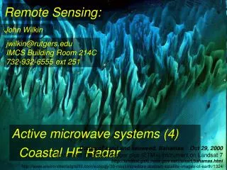
Remote Sensing:. John Wilkin. jwilkin@rutgers.edu IMCS Building Room 214C 732-932-6555 ext 251. Active microwave systems (4) Coastal HF Radar.

Remote Sensing:
E N D
Presentation Transcript
Remote Sensing: John Wilkin jwilkin@rutgers.eduIMCS Building Room 214C732-932-6555 ext 251 Active microwave systems (4) Coastal HF Radar Dunes of sand and seaweed, Bahamas Oct 29, 2000Enhanced Thematic Mapper plus (ETM+) instrument on Landsat 7http://landsat.gsfc.nasa.gov/earthasart/bahamas.htmlhttp://www.environmentalgraffiti.com/ecology/30-most-incredible-abstract-satellite-images-of-earth/1324
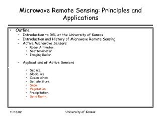
Scatterometers • satellite borne • ocean surface vectors winds • Incorporated into ECMWF meteorological analysis • Synthetic Aperture Radar (SAR) • satellite and aircraft • high spatial resolution (tens of meters) • image ocean surface wave field and, by inference, processes that modulate the surface waves • CODAR (Coastal Ocean Dynamics Application Radar) • land-based HF radar system • ocean surface currents and waves • All these systems exploit the resonant “Bragg” scattering of centimeter to decameter wavelength microwave radiation from ocean surface roughness due to short waves.
Quikscat scatterometer frequency is 13.4 GHz = 2 cm wavelength HF Radar is 3 – 50 MHz = 100 m to 6 m
http://www.codaros.com CODAR • High-frequency (HF) radio in the band 3-50 MHz has wavelengths6 m to 100 m • The ocean surface is rough surface, with water waves of many different periods • Bragg scattering occurs for narrow band of wavelengths depending on CODAR frequency • 25 MHz transmission -> 12m EM wave -> 6 m ocean wave12 MHz transmission -> 25m EM wave -> 12.5 m ocean wave 5 MHz transmission -> 60m EM wave -> 30 m ocean wave • Radar return is greatest for waves traveling directly toward or away from the antenna • Therefore we know wave direction and wavelength http://www.encora.eu/coastalwiki/Use_of_ground_based_radar_in_hydrography
From surface gravity wave dispersion theory we know the wave period and hence wave speed • The phase speed C of these resonant ocean waves is given by the dispersion relationship: • Where g is the acceleration due to gravity, λ is the ocean wave length, and h is the water depth. • Wave speed creates a Doppler frequency shift in the radar return
From surface gravity wave dispersion theory we know the wave period and hence wave speed • Wave speed creates a Doppler frequency shift in the radar return • In the absence of ocean currents, the Doppler frequency shift would always arrive at a known position in the frequency spectrum • Observed Doppler-frequency shift includes the theoretical speed of the speed of the wave PLUS the influence of the underlying ocean current on the wave velocity in a radial path (away from or towards the radar) • Once the known, theoretical wave speed is subtracted from the Doppler information, a radial velocity component of surface current is determined. • The effective depth of the ocean current influence on these waves depends upon the wave period and wave length. The current influencing the Bragg waves falls within the upper meter of the water column. • By looking at the same patch of water using radars located at two or more different viewing angles, the total surface current velocity vector can be resolved
Doppler shift due to waves when no current is present Side lobes from antenna beam pattern Added Doppler shift due to current
A SeaSonde HF radar unit has onetransmitting antenna and one receiving antenna • The transmitting antenna is omni-directional- it radiates a signal in all directions • The receive antenna unit consists of three colocated antennas, oriented with respect to each other on the x, y, and z-axes (like the sensors on a pitch and roll buoy). It is able to receive and separate returning signals in all 360 degrees • For mapping currents, the radar needs to determine three pieces of information: • bearing of the scattering source (the target) • range of the target • speed of the target
A SeaSonde HF radar unit has onetransmitting antenna and one receiving antenna • The transmitting antenna is omni-directional- it radiates a signal in all directions • The receive unit consists of three co-located antennas, oriented with respect to each other on the x, y, and z-axes (like the sensors on a pitch and roll buoy). It is able to receive and separate returning signals in all 360 degrees • For mapping currents, the radar needs to determine three pieces of information: • bearing of the scattering source (the target) • range of the target • speed of the target
The first determination is Range to target. • The SeaSonde modulates the transmitted signal with a swept-frequency signal and demodulates this in the receiver • the time delay is converted to a large-scale frequency shift in the echo signal • Therefore, the first digital spectral analysis of the signal extracts the range (distance) to the sea-surface scatterers, and sorts it into range bins (typically 5 km) • the frequency shift of transmitted minus received signal contains time lag and range information
The frequency shift of transmitted minus received signal contains time lag and range information
The second determination is Speed of the target. • the signal is processed for ~ 4 minutes to produce an average spectrum from which the Doppler shift is calculated • this gives speed accuracy of ~ 4 cm/s • The third determination is Bearing of target • the receive antenna has 2 directional ‘loop’ antennas and 1 omni-directional whip antenna • the loop antenna patterns receive power differently from the same incoming direction • processing the signal difference from the 2 loop antennas, normalized by the omni-directional antenna, performs the direction finding
Beam forming approach for direction determination– phased array antennas
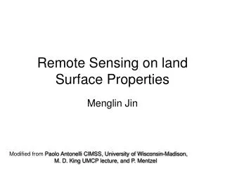
Spatial Maps 10/16/2002 0700 GMT RUC Wind and Pressure Analysis CODAR Surface Currents 1002 mb Contour resolution – 1 mb
RUC Wind and Pressure Analysis CODAR Surface Currents L L 10/16/2002 1500 GMT 991 mb Contour resolution – 1 mb
RUC Wind and Pressure Analysis CODAR Surface Currents L L 10/16/2002 1800 GMT 989 mb Contour resolution – 1 mb
RUC Wind and Pressure Analysis CODAR Surface Currents L L 10/17/2002 0000 GMT 992 mb Contour resolution – 1 mb
Georges, T.M., and J.A. Harlanhttp://ieeexplore.ieee.org/stamp/stamp.jsp?arnumber=00569128