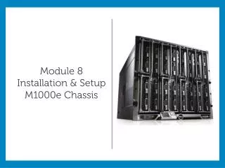
Module 8 Installation & Setup M1000e Chassis
Module 8 Installation & Setup M1000e Chassis. <Place supporting graphic here>. Module Objectives:. Installation of the M1000e platform, including the weight of the unit, both fully loaded and empty. PowerEdge Field Replaceable Units (FRUs).

Module 8 Installation & Setup M1000e Chassis
E N D
Presentation Transcript
Module 8 Installation & Setup M1000e Chassis <Place supporting graphic here>
Module Objectives: • Installation of the M1000e platform, including the weight of the unit, both fully loaded and empty. • PowerEdge Field Replaceable Units (FRUs). • Overview of redundant and non-redundant power configurations. Such as advanced power management and AC and power supply configurations.
Installation • The M1000e is heavy. • Up to 390lbs loaded. • Empty 98lbs • Ships with all modules installed. • REMOVE all modules following before lifting including: • Power supplies • Server blades • I/O Modules • Do not attempt to lift alone! • Use the handles located on the sling provided
Rack Mounting • Requires 10 U of rack space, mark installation location • Up to four units can be installed in one rack • Mount RapidRails or VersaRails assembly • Re-install and secure all modules • Setup cable management • Connect and bundle cable • Use the I/O Cable Enumerators • Secure cables to the Strain-Relief Bar
Hot Swap FRU Components • CMC • iKVM • Blades • I/O Modules • Fan • PSU
Module Buttons and Handles Press Button to Release Handle or Module
Blanking Plates CMC blanking plate IOM blanking plate PSU blanking plate
M1000e Power • Up to six 2700 watt PSU’s may be installed. • 94%+ AC/DC Conversion Efficiency. • PSUs operates on 200-240v AC power. • Though supported, use of 110-120v AC power not recommended • Update CMC if using 110-120v AC • Dell does not support the mixing of 230V and 115V within the same enclosure. • Active PSUs are load sharing. • Total system redundant power is approximately 8100w in a 3+3 power supply configuration. • AC redundancy is supported in the following configurations, each of which requires the power supplies in slots 1, 2, and 3 to be connected to a different grid as compared to those in slots 4, 5, and 6.
Turn On System Press the power button on the enclosure. The power indicator should light.
Turning On Blades Press the power button on each blade, or power on the blades using the systems management software.
M1000e Power Subsystem The M1000e ships with a minimum of three PSUs in a non-redundant configuration. • Three PSUs needed to power a full chassis • For redundancy, a minimum of four PSUs recommended • Dell recommends fully populating the enclosure with six PSUs.
AC Redundancy Configurations Dual Power Grid: • Protects against failure to an AC grid • Protects against failure to up to 3 power supplies
Power Supply Redundancy Configuration Dual or Single Power Grid: • Power Supply Redundancy protects against failure to a single power supply.
No Redundancy Configuration Single Power Grid: • No protection against grid or power supply failure
Module Summary • After completing this module you should now be able to: • Describe the steps to safely install an M1000e. • Identify hot swappable components. • Describe the power specifications associated with the M1000e enclosure. • Understand how to power on both the M1000e enclosure and the blade servers. • Describe the various M1000e power options, including redundant and non-redundant AC grids and power supplies configurations.