Development of PLC Front-End Reference Design at Texas Instruments
This project focuses on the creation of a PLC Front-end reference design aimed at enhancing analog applications. As part of a co-op term at Texas Instruments, I developed schematic designs, optimized layouts, and conducted rigorous testing for various analog sensors including thermistors, RTDs, and thermocouples. My objectives included hands-on experience with analog circuit design, application engineering insights, and understanding the role of TI in the automation industry. This process involved a detailed calibration of sensor inputs to ensure high accuracy in temperature readings and voltage measurements.


Development of PLC Front-End Reference Design at Texas Instruments
E N D
Presentation Transcript
PLC Front-end Curtis Mayberry Texas Instruments HPA Linear Applications 8/19/11
Background • Student at Iowa State University • Originally from Ames, IA • Interest in Analog applications and design • Graduating December 2011
Coop Term Goals • Complete PLC Front-end reference design including: • Schematic • Layout • Testing • Documentation • Continue developing analog circuit analysis skills • Create a board-level analog circuit design • Learn about applications engineering and its role in TI’s business • Learn about TI as an employer
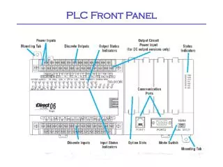
Programmable Logic Controller • Programmable automation controller • Used in a variety of industries including the automotive, chemical, and food industries • Microcontroller offers reprogrammable real-time control solution • 4 major Components: • Power supply • Controller • Communications • Input/Output • Universal voltage Input: 0-5v, ±5v, 0-10v,±10v • Current loop sensor communication: 0-20mA, 4-20mA • Temperature sensors: thermistor, RTD, thermocouple • Pressure, flow, level, vibration and motion sensors • Digital I/O (GPIO) • Analog Output (DAC8760)
Motivation • #1 collateral request from FAEs • Existing ADI reference design • Customer Requests and New Customer Opportunities
Project Definition • PLC Analog Front-End • Focus on analog Inputs: • Universal voltage Input: 0-5v, ±5v, 0-10v, ±10v • Current loop sensor communication: 0-20mA, 4-20mA • Temperature sensors: thermistor, RTD, thermocouple • SM-USB-Dig controller • Labview Interface to SM-USB-Dig • Documentation • Create design review and final presentation • Ensure a smooth transition to next stage of project
Block Diagram Stage 1 Stage 2 RTD TC Thermistor +/-10v, +/-5v 4-20mA Microcontroller ADC Signal Conditioning High-Accuracy Stage 1 Only DAC Super-Mini Dig Labview
Schematic • Schematic design review • Minor schematic design revisions made following review
Layout • Optimized Analog inputs • Short, symmetric traces • Recessed power and control circuitry
Board Assembly and Troubleshooting • No Errors in Analog Front-end • Assembled V and I Front-end for early software development • Minor Errors contained in power and Control circuitry • Five known errors: • Pull up resistors on LDO EN pins • Move pull up on digital switch (trace needed to be cut) • Ground connection needed to SM-USB-DIG • Need to move SM-USB-DIG connector closer to edge of board • Need pull-up resistors on CS lines
Software • Started with SM-Dig shell • Added CS control to select front-end • Added DMM Control • Added Data logging • Added Data Displays for 6 front-ends • Added configuration capabilities for all 6 front-end modules Labview Interface Front Panel Labview Interface DMM Control
Testing: Temperature Sensing • All Temperature Sensors were submerged and read between 0 oC and 125oC • Thermal bath wasn’t settling at negative temperatures • Post-processed 3 point calibration
Thermistor Input (Direct) • Uncalibrated Worst Case Error: 0.4 oc • 3 point Calibration (35oc, 65oc, 105oc) • Calibrated Worst Case Error: 0.3 oc • 0.24% accuracy
Thermistor B Input (Bridge) • Uncalibrated Worst Case Error: 0.9 oc • 3 point Calibration (35oc, 65oc, 105oc) • Calibrated Worst Case Error: 0.38 oc • 0.304% Accuracy
RTD Input • Outlier Removed at 15oC • Uncalibrated Worst Case Error: 0.9 oc • 3 point Calibration (35oc, 65oc, 105oc) • Calibrated Worst Case Error: 0.015 oc • 0.012%
Thermocouple • Uncalibrated Worst Case Error: 1.2 oc • 3 point Calibration (35oc, 65oc, 105oc) • Calibrated Worst Case Error: 0.4 oc • 0.32% error
Results: Temperature Sensing Maximum calibrated Error 0oC – 125oC • Thermistor: 0.3oC • Thermistor B: 0.38oC • RTD: 0.015 oC • Thermocouple: 0.4oC
Testing: Universal Inputs • Post-processed 3 point calibration • Tested using a Fluke precision voltage and current source in 0.5 V or 0.5 mA step size • Input measured using HP 8.5 digit digital multimeter
Universal Voltage: ±10v • Outlier Removed at 5.5 V • Uncalibrated Worst Case Error: 10 mV • 0.05% Accuracy • 3 point Calibration (-6v, 0v, 6v) • Calibrated Worst Case Error: 0.153 mV • 0.000765% Accuracy
Universal Voltage: 0 - 10v • Outlier Removed at 5.5 V • Uncalibrated Worst Case Error: 10 mV • 0.1% Accuracy • 3 point Calibration (2v, 5v, 8v) • Calibrated Worst Case Error: 0.35 mv • 0.00175% Accuracy • Worse than +/-10v
Universal Voltage: ±5v • Outlier Removed at -0.5 V • Uncalibrated Worst Case Error: 3 mV • 0.03% Accuracy • 3 point Calibration (-3v, 0v, 3v) • Calibrated Worst Case Error: 0.25 mV • 0.0025%
Universal Voltage: 0 - 5v • Uncalibrated Worst Case Error: 2.5 mV • 0.05% Accuracy • 3 point Calibration (0.5v, 2.5v, 4.5v) • Calibrated Worst Case Error: 0.15 mV • 0.003% Accuracy
Current Loop: 4-20 mA • Uncalibrated Worst Case Error: 1.8 uA • 0.0115% • 3 point Calibration (6.5mA, 12mA, 17.5mA) • Outlier removed at 14mA • Calibrated Worst Case Error: 2.5 uA • 0.0156% • Calibration ineffective due to no consistent gain or offset error, main error component is current source • Change in Error when the source changed output range
Current Loop: 0-20 mA • Uncalibrated Worst Case Error: 22uA • 0.11% Accuracy • 3 point Calibration (3.5mA, 10mA, 16.5mA) • Calibrated Worst Case Error: 21 uA • 0.105% Accuracy
Results: Universal Front-Ends Calibrated maximum error: • Universal V • ±10 v: 0.153 mV • 0-10 v: 0.35 mV • ±5 v: 0.25 mV • 0-5 v: 0.15 mV • Current Loop • 4-20 mA: 2.5 uA • 0-20 mA: 21 uA
Accomplishments • Completed PLC Front-End Design • PLC Research • Sensor Research • Component Selection • Schematic Design and Review • Layout Design and Review • Fabrication • Software • Debugging • Testing • Completed Forum Post • Learned a lot about board-level development, Op-amps, and about TI’s business
Other Accomplishments • Volunteered: • Day of Hope • Disability Connection Carnival • Networked with teammates and other coops • Learned about analog applications • Learned about the relationship between field and factory applications engineering • Developed a better understanding of all the engineering roles
Project Continuation and Career Plans Final Goal: Complete PLC Reference Design utilizing TI parts • Progress will continue during second stage • Potential Microcontroller TI 32-bit Stellaris LM3S1Z16 • Potential output DAC: DAC8760 Career Plans: • Attend graduate school for analog design • Return to TI for another Coop Experience as a graduate student
Feedback • Great Project • Interesting and rewarding • Well-defined and complete • Excellent Mentoring by Pete and Collin • Given Freedom to work independently while still having support available • Great job with on-boarding and providing the resources I needed • Great teachers for both Technical and non-technical material • AFA conference and Tucson Testing Trip were Great Opportunities • CORT relocation service hard to work with before coming to TI
Thank You • Special Thank You to my mentors: Collin Wells Pete Semig • Also to my managers: Art Kay Matt Hann • Data Converter Applications Team Tom Hendrick, Greg Hupp, Kevin Duke, Tony Calabria
Appendices • Appendix A: Elaborated Testing Results • Appendix B: Design review
Appendix A: Elaborated Testing Results Calibration Curves, raw data plots, resistance plots