Download
1 / 76
760 likes | 877 Vues
The KEKB B-Factory achieved world-highest peak and integrated luminosities, concluding operations on June 30, 2010, after extensive development. Key components included superconducting cavities, crab cavities, and skew-sextupole magnets, significantly boosting luminosity by around 20% despite geometric losses from crossing angles. The implementation of crab cavities allowed efficient beam crossing at 11 mrad, effectively increasing the beam-beam parameter. The upgrade toward SuperKEKB marks a new chapter following 13 years of research and development, showcasing innovative advancements in high-energy physics.

E N D
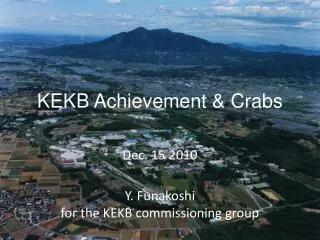
KEKB Achievement & Crabs Dec. 15 2010 Y. Funakoshifor the KEKB commissioning group
Superconducting cavities (HER) Belle detector e- KEKB B-Factory e+ ARES copper cavities (HER) ARES copper cavities (LER) TRISTAN tunnel 8 GeV e- 3.5 GeV e+ Linac e+ target KEKB B-Factory Crab cavities 1 for each ring • ♦World-highest Peak Luminosity • 2.11 x 1034cm-2s-1 • Twice as high as design value • ♦World-highest Integrated Luminosity • Total: 1040fb-1as of June 30th 2010 ♦Crab crossing (f = 11 mrad) ♦Skew-sextupole magnets The KEKB operation was terminated at the end of June 2010 for theupgrade toward SuperKEKB.
Finally two crab cavities were installed in KEKB,one for each ring in January 2007 HER (e-, 8 GeV) LER (e+, 3.5 GeV) …..after 13 years’ R&D from 1994
skew-sextupoles 1040
Structure of KEKB Crab Cavity Top View Input coupler Frequency Tuning by Adjusting Distance Magnetic Shield ( Jacket Type) RF Absorber RF Absorber Stub Support I.D. 240 Coaxial Coupler I.D.100 Crab mode: TM110: By on beam axis Lower mode: TM010: dumped through coaxial coupler Squashed cell shape to split TM110 modes Crab Mode Reject Filter Liq. He Bellows Monitor Port Liq. He 80 K LN2 Radiation Shield
Single Crab Cavity scheme Beams tilt all around the rings. -> z-dependent horizontal closed orbit • 1 crab cavity per ring. • Saves the cost of the cavity and cryogenics. Tilt at the IP:
Beam-Beam Simulations • Crab Crossing can boost the beam-beam parameter higher than 0.15 ! (K. Ohmi) Head-on (crab) Strong-strong beam-beam simulation 22mrad crossing angle } Head-on y ~0.15 nx =.508 • After this simulation appeared, the development of crab cavities wasrevitalized. With the crab crossing, the beam-beam parameter and then the luminosity would be doubled !!
Chromaticity of x-y coupling at IP • Ohmi et al. showed that the linear chromaticity of x-y coupling parameters at IP could degrade the luminosity, if the residual values, which depend on machine errors, are large. • To control the chromaticity, skew sextupole magnets were installed during winter shutdown 2009. • The skew sextuples are very effective to increase the luminosity at KEKB. • The gain of the luminosity by these magnets is ~15%.
Specific luminosity (crab on/off) with skew sextuples Luminosity improvement by crab cavities is about 20%. Geometrical loss due to the crossing angle is about 11%.
Calculation of beam-beam parameter • Reduction factor for beam-beam parameter • 2 sources of reduction • hourglass effect and finite crossing angle Montague’s factor
Calculation of beam-beam parameter [cont’d] • Reduction factor for luminosity • Luminosity • We use calculated values for x* and calculatey* and y0 from observed luminosity.
Effectiveness of crab cavities • The crab cavities at KEKB did work and brought the luminosity increase by ~20%. This is larger than the geometrical loss (~11%) due to the crossing angle. • The highest luminosity with crab is 2.1 x 1034 cm-2s-1. • Skew-sextupoles • Increase of HER beam current by solving the physical aperture problem • There still exists a large discrepancy between the luminosity achieved and the beam-beam simulation. • The simulation predicted that the luminosity would be doubled. • Side effects of large tuning knobs to compensate the machine errors? • We will have no opportunity to investigate the reason for this.
K. Akai Crab system Adjustment • Crab voltage • Calibrated from klystron output power and the loaded Q value. • The measurement to change the phase using beam also gives an independent calibration of the voltage. • Both are in good agreement within a few percent. • In addition, a crab voltage scan is done to maximize the luminosity in the luminosity run. • Crab phase • The reference phase is searched to minimize the beam orbit difference between the crab on and off, so that the bunch center is not kicked by the crab voltage. • In the high-current operation,the phase is shifted by 10 degrees from the reference phase to cure the oscillation observed at high-current crab collision. • Field center in the cavity • Searched by measuring the amplitude of the crabbing mode excited by a beam when the cavity was detuned. A local bump orbit was set to adjust the beam orbit on the cavity axis.
H. Koiso, A. Morita 72 108 36 144 360 0 180 324 216 288 252 Crab Phase Scan (LER) Horizontal orbit by crab kick crab crab Horizontal kick by crab cavity (rad) (Estimated from orbits around the ring) Phase 0:174.8 deg. Vcrab set:1.0MV, estimated: 0.987MV agree very well To find the zero-cross point of crab Vc, the crab phase scan is done.
Oscillation of High-current Crabbing Beams • A large-amplitude oscillation was observed in high-current crab-crossing operation in June 2007. • It caused unstable collision, short beam lifetime and luminosity degradation. • The crab voltage and phase were modulated at ~540 Hz. A horizontal oscillation of beams was also observed at the same frequency. • None of the beam orbit feedback systems is responsible, since their time constants are 1 to 20 sec, much slower than the oscillation. • The oscillation occurred when the LER tuning phase migrated to the positive side. This gave us a hint to understand the phenomena. Beam-beam kick is shaken. K. Akai
HER tuning offset: φtun (HER) φtun (HER) = +10° oscillation occurs LER tuning offset (degree) φtun (HER) = 0° φtun (HER) = -10° Both crab phase (degree) stable A Remedy for the Oscillation was found. • Observations at a machine study • The oscillation occurred only with high-current colliding beams: it never occurred with a single beam, even at a high current. • Both beams oscillates coherently. • The threshold for the oscillation is dependent on the crab phase and tuning phase (see left). • Cause and remedy • We concluded that the oscillation is caused by beam loading on crab cavities together with beam-beam force at the IP (see, next slide). • We found that it can be avoided by shifting the crabbing phase by +10° and controlling the tuning offset angle appropriately. Dependence on the crab phase and tuning phase. Beam current was 1150 mA (LER) and 620 mA (HER). K. Akai
Phase control LER Kick bunch Crab phase Input rf phase Horizontal displacement at crab and IP Crab voltage Input rf power Level control Beam-loading on crab cavity IP Kick by beam-beam force Phase control HER Kick bunch Crab phase Input rf phase Horizontal displacement at crab and IP Crab voltage Input rf power Level control Beam-loading on crab cavity Possible mechanism of the oscillation K. Akai
Physical aperture issues • Large mis-alignment? • We found that the field center of the HER crab cavity is ~6.5mm deviated from the BPM center. • Effect to beam lifetime • In case of beam collision, we found that the beam lifetime was determined by the physical aperture around the crab cavity for both beams at high bunch currents. • In KEKB, the dynamic beam-beam effects (dynamic beta and dynamic emittance) are very serious. • We tried to raise the crab voltage by lowering He temperature. However, this trial was not successful. • We could mitigate this problem by enlarging the bx* from 0.9m to 1.2m. By doing this, we could increase the HER beam current. This brought some increase in the peak luminosity.
Aperture survey around HER crab • Scan of HER Crab Alignment Bump • Original bump height: ~-6.5 mm necessary to minimize the beam loading • Higher bumps made the lifetime longer (peak at a bump with Δx = ~ -4mm). • Mis-alignment of HER crab cavity? • After the machine was shutdown, we actually found a mis-alignment of the HER crab cavity which is consistent with the original bump height. • Necessity of the additional 4mm bump is still a mystery. I+ x I- ~1.5mA2 Alignment Bump Crab Cavity ~ 4mm original height Life peak 10
LER dynamic- and emittance Horizontal beta function at IP
crab LER Beta’s with dynamic beam-beam effect with/without beam-beam effects crab HER
CAVITY VOLTAGE DROP OF LER CRAB Cavity voltage of LER Crab was better than HER at horizontal test. But, after installation to beam line, it dropped gradually. And, it dropped suddenly from 1.3 to 1.0MV in Mar/17/2007. black day The sudden drop of LER crab voltage has never recovered until the end of KEKB operation. Y. Yomamoto
LOWER TEMPERATURE OPERATION PKly Hosoyama-san’s group tried lower temperature operation than 4.2K. First trial was done in autumn/2008. It failed due to unexpected oil reduction of pumping system. Second trial was done in spring/2009. Lower temperature operation was successful! The operation was stable around 3.6K. But, performance of LER Crab cavity was not recovered. Vkick He Temp. He Level He press. at cavity He press. at pump Y. Yomamoto
Orbit Control and Feedback near Crab Cavities • We have chosen QL=1~2 x10⁵ for a good compromise. • This value is suitable for operating the system with a possible error of ΔX=1mm, and • A high power source of 200 kW is sufficient for conditioning the cavity up to 2 MV. Dependence of RF power on the loaded Q value and a horizontal beam orbit for a beam current of 2 A. Typical parameters for the crab crossing. • ★Orbit feedback around crab cavities • Only horizontal orbit feedback is considered. • 4 horizontal steering magnets to make an offset bump for each ring • 4 BPMs to monitor the offset at the crab cavity. 2 upstream (entrance) BPMs and 2 downstream (exit) System speed (design) <~1 Hz. • We found that the orbit is stable enough.Usually, we do not need the orbit feedback.
RF Trips of Crab Cavities Period 1 : Feb/2007~Jun/2007, Period 2 : Oct/2007~Dec/2007, Period 3 : Feb/208~Jun/2008 Period 4 : Oct/2008~Dec/2008, Period 5 : Apr/2009~Jun/2009, Period 6 : Oct/2009~Dec/2009 Lower crab Vc (HER) 1.4 -> 1.3MV 2.8/day 0.4/day 0.8/day 0.1/day 558days HER : 1.3/day LER : 0.5/day RF trip of LER Crab was very small last year. Total average Y. Yamamoto
Crab Cavity I/L System Breakdown detector judges whether Pkly, VC and φcrab (only VC for LER) are normal, or not. If not, Crab RF is switched off. This is the most frequent cause of Crab RF trip. Breakdown detector RF output from pickup probes Several pickup probes are attached for monitoring the transmit power and the RF output at coaxial beam pipe. Vacuum Temperature Crab RF Off Beam abort Arc sensor Whenever Crab RF is switched off, the beam is aborted coincidently, because of safety. He pressure/level Flow rate of cooling water Most of cases of HER trips are breakdowns of superconductivity due to discharge in the cavity. On the other hand, causes of LER cavity are discharge in the coaxial coupler or at the input coupler. Y. Yamamoto
What happens in case of Crab RF Trip? Beam positions of aborted beam RF off 1. D11-F klystron out reference 2. D11-F cavity voltage Beam Abort 3. D11-F cavity tuner phase 4. HER DCCT Y. Morita 20090422 7:38 HER Vc abort Typical example when HER Crab RF trips. HER beam current: 750 mA We abort the beam and switch-off the crab RF in case of crab RF trip. In some cases, the beam is kicked more largely by the crab after RF trip and before RF off. One of my colleagues (Nakanishi) are studying the transient behavior of the beam.
RF phase shifts 50 degree in 50 μsec after the RF stop -> Nakanishi’s talk (tomorrow)
LER crab phase ± 1 deg HER crab phase Phase stability • Spectrum of pick up signal is consistent with phase detector data. • Phase fluctuation faster than 1 kHz is less than ± 0.01°, and slow fluctuation from ten to several hundreds of hertz is about ± 0.1°. • They are much less than the allowed phase error obtained from the beam-beam simulations for the crabbing beams in KEKB. According to b-b simulation by Ohmi-san, allowed phase error for N-turn correlation is 0.1×√N (degree). Span 500 Hz Sideband peaks at 32, 37, 46, 50, 100 Hz. Span 10 kHz Span 200 kHz Sideband peaks at 32kHz and 64kHz. Phase detector signal. Beam current was 385mA (HER) and 600 mA (LER). Spectrum around the crabbing mode measured at a pick up port of the LER crab cavity. Beam current was between 450 and 600 mA. Rogelio’s Talk (tomorrow) K. Akai
Measurements or experiences on impedance related issues • The following measurements were done before and after the installation of crab cavities (by T. Ieiri). • Bunch current dependence of coherent tune shift • Loss factor • Bunch lengthening as function of the bunch current • No significant difference was observed on these measurements between before and after crab. • We once observed a coupled bunch instability due to the crabbing mode. However, this was due to wrong setting of the detuning frequency. • As for the HOMs or LOMs, we have not experienced that they induced any coupled bunch instability.
Crab Vc scan • The scan was done in HER on Dec. 24th 2009. • The beam current was 800mA (single beam). • The crab voltage was changed from 1.4MV to 0.5MV and from 0.5MV to 1.4MV. • No beam loss and change of beam sizes were observed.
SuperKEKB • We have decided to change the design concept of SuperKEKB from the High-Current scheme to the Nano-Beam scheme (Italian scheme) at the beginning of 2009. • No crab cavities will be needed for SuperKEKB with the Nano-Beam scheme.
Reasons for change of schemeHigh-Current to Nano-Beam • Luminosity gain with crab cavities • The beam-beam parameter of 0.15 which was predicted by the beam-beam simulation was not achieved. • Difficulty of CSR • We need travelling focus scheme to achieve the design luminosity with the high current scheme. • IR design • No solution for realistic IR design with bx* = 20cm was found. • Budget constraint
Comparison of parameters 1 (Oku-Yen) = 1.23 M USD = 0.88 M EUR (as of 6 Nov., 2010)
Field measurement Conditioning Design Design Layout change / Add stations / Cavity improvements QCS fabrication Install & test Design & Fabrication Design / Fabrication QCS prototype Fabrication TiN coating Fabrication Cabling / Check Building construction Cooling system Install Install Install Alignment Test Remove magnets and beam pipes Base plates SuperKEKB Main Ring schedule Oct. 20, 2010 FY2010 FY2011 FY2012 FY2013 FY2014 FY2015 KEKB operation MR commissioning Tunnel clear Physics Run Beam pipes (LER) Beam pipes (HER) Magnets & Power supplies Beam monitors and Control RF system IR hardware Infrastructure K. Akai Dismantlement of the LER ring started in this autumn.
Summary • The crab cavities at KEKB have been working much more stably than the initial expectation. • They have been used in usual physics run. • The crab cavities at KEKB did work in the sense that the luminosity gain with the crab cavities is much larger than the geometrical loss due to the crossing angle. • There still exists a large discrepancy between the beam-beam simulation and the experiment with the crab crossing. • We have 3-year’s experiences of the beam operation with crab cavities and hope that these experiences are useful for other laboratory . • The KEKB operation was terminated at the end of June 2010. • In SuperKEKB, we will not employ the crab cavities. • The budget of SuperKEKB has been partially approved and we started the construction of SuperKEKB.
Cost estimation (Accelerator part) 1 (Oku-Yen) = 1.23 M USD = 0.88 M EUR (as of 6 Nov., 2010) • Cost for Belle upgrade is not included in the list. K. Akai
Approved budget • Damping ring: 5.8 Oku-Yen (FY 2010) • Special budget (Saisentan-Kiban-Jigyou):100 Oku-Yen (3-years from FY 2010) • Beam pipes for positron ring (57 Oku-Yen) • Magnet system for positron ring (43 Oku-Yen)