Download
1 / 1
10 likes | 108 Vues
This IEEE workshop explores challenges and solutions in mobile parallel relays from a networking perspective. Topics include throughput optimization, power saving strategies, and packet transmission efficiency. The session addresses issues such as maintaining robust connections in mobile ad hoc networks and managing fast SNR fluctuations due to high node mobility. The use of space-time modulation/coding, relay synchronization, and route finding algorithms for parallel relays is discussed, with a focus on enhancing connection reliability and power efficiency in wireless communications.

E N D
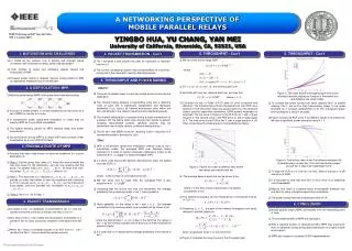
A NETWORKING PERSPECTIVE OF MOBILE PARALLEL RELAYS IEEE Workshop on DSP, Taos Ski Valley, NM, 1-4 August 2004 YINGBO HUA, YU CHANG, YAN MEI University of California, Riverside, CA, 92521, USA . q We can show that for large SNR, 1. MOTIVATION AND CHALLENGE 5. THROUGHPUT - Con’t 4. PACKET TRANSMISSION - Con’t 5. THROUGHPUT - Con’t • q Tier t transmits a new packet only after an instruction is received from tier t+1. • q The control (scheduling) signals may be transmitted via channel(s) orthogonal to the channel(s) used for data transmission. • qIn mobile ad hoc network, how to achieve and maintain robust connection with constraint on delay, power and bandwidth? • q High mobility of nodes and interfering objects causes fast fluctuations of SNR. • Frequent power control or frequent network routing based on SNR (or equivalent) feedback may not be efficient. where q For , d(t)=N2, i.e., the diversity gain is N2. 5. THROUGHPUT AND POWER SAVING q Note that with only two relays at each link, we have that q Mobile parallel relays (MPR) with space-time modulation/coding: . 2. A DSP SOLUTION: MPR Figure 3: The lower bound of throughout gain from serial relaying to parallel relaying as function of the packet loss rate between two single nodes. • Assume: • q There are N parallel relays in each tier except at the source and the destination. • The channel fading between a transmitting node and a receiving node at each link is statistically independent and identically distributed (i.i.d.) across all transmit-and-receive pairs within the link, and all links in the network have the same statistical property. • The channel fading factor is constant during a single transmission of a packet. But the fading factor may change from packet to packet, including retransmitted packets. (Multiple packets may be transmitted over multiple carriers of different fading factors.) • The bit error rate (BER) at the ith receiving node in response to k transmitting nodes is denoted by pi(k). q To consider the power saving from serial relaying (N=1) to parallel relaying (N>1), we let the total transmission power to be upper bounded by a constant independent of N. The orthogonal space-time modulation is used in all cases. q Figure 4 shows the PLR at tier 5 for different values of N at each tier. We see a significant power saving by using N > 1. q Consider the use of Golay (24,12) code for error correction and detection. The following figure shows the packet loss rate (PLR) as a function of SNR where two relays are used at each tier. The Alamouti code is used for space-time modulation. QPSK symbol modulation is assumed. The top curve in Figure 2 is the PLR at tier 1, with a slope equal to 2. The second curve is the PLR at tier 2, with a slope equal to 3. The third curve is the PLR at tier 3, with a slope equal to 4. All other curves have the slope equal to 4 as predicted by theory. • q A cluster of nodes present in a small neighborhood may serve as a set of MPR for one link of a route. • In transmission mode, space-time modulation or codes may be used by MPR as if by multiple transmitters. • The spatial diversity gained by MPR reduces delay and power consumption. • q Synchronization among MPR is a unique DSP issue currently under investigation by a joint UCR/UCLA team. • . Then: q With a full-diversity space-time modulation method used at the ktransmitting nodes, the averaged BER over Rayleigh fading channels for a class of symbol modulation methods is known to be proportional to for large (averaged) SNR. q If a block code and a hard decision decoding are used, the packet loss rate (PLR) is 3. FINDING A ROUTE OF MPR • Assume that each node knows its next-hop neighbors for a given destination D. • qStep 0: Set the group (tier) index t=0. Since the source knows the next-hop relays for the destination, we can now assume that the group t of parallel relays Rt(1), Rt(2), …, Rt(Nt) all know their next-hop relays , Rt+1(1), Rt+1(2), …, Rt+1(Nt+1). (Note N0 =1) • qStep 1: The lead relay Rt(1) requests Rt+1(1), Rt+1(2), …, Rt+1(Nt+1) to provide (in order) their tables of next-hop neighbors with reference to D. Rt(1) figures out Rt+2(1), Rt+2(2), …, Rt+2(Nt+2) as the intersect of those tables, and then provides this information to Rt+1(1), Rt+1(2), …, Rt+1(Nt+1). • qStep 2: Set t=t+1. Go to Step 1. Figure 4: Packet loss rates at tier 5 for different numbers (N) of parallel relays at each tier. The total transmission power at each tier is kept to be independent of N. Figure 2: Packet loss rates at different tiers where two relays are used at each tier • q To keep the PLR at 1% from N=1 to N=2, there is almost a 10 dB reduction of SNR. • q It is important to note that from N=1 to N=2, there is no additional cost of bandwidth. • Beyond N=2, there is a penalty factor of bandwidth (between one and two) for using orthogonal space-time modulation. • q The power saving becomes insignificant when N >4. • We can show that for large SNR, the averaged PLR is also proportional to • qAssuming that the source has only one transmitter, the average probability that g receiving relays in tier 1 lose a packet is where c is the number of correctable error bits. • q The average delay at each link can be shown to be • where D is the time of each transmission of a packet, • successfully or not. • q The network throughput can be measured by a normalized inverse of Tt(N), i.e., • Assuming Pk+1< Pk , the gain of the network throughput from serial relaying to parallel relaying is • which is significant whenP1 is not very small. • q Figure 3 illustrates the lower bound of the throughput gain. qMore generally, for the relays in tier t and , the average probability that g receiving relays lose a packet can be shown to be 4. PACKET TRANSMISSION 6. CONCLUSION • q A packet in tier t is repeatedly re-transmitted to tier t+1 until the packet is received correctly by at least one relay in tier t+1. • Any relay in tier t+1 can initiate the transmission (forwarding) of a packet to tier t+2 upon successful reception of the packet from tier t. • When tier t hears a forwarded packet or an ACK from t+1 , tier t decides that tier t+1 has received the packet correctly. • Mobile parallel relays (MPR) are feasible from the networking point of view. • q The potential benefits of MPR are significant. • q With a reduced burden on networking traffic, MPR may yield more than 10 dB power saving during data transmission in a highly mobile environment. • q MPR also hinges on successful DSP implementations. where the denominator 1-Gt-1(N) is due to the fact that the relays in tier t-1 do not forward a packet until at least one of them received the packet correctly q It is clear that Gt(N) measures the average probability of link failure in tier t. This work is supported in part by the ARL’s CTA program.