Download
1 / 50
500 likes | 637 Vues
Noise Integrated Routing System (NIRS) NIRS Screening Tool (NST). Airspace Environmental Workshop September 20, 2007. Today’s Objectives. Background & NIRS/NST Overview NIRS Screening Tool (NST) Conceptual Overview Usability/Demonstration NIRS Conceptual Overview Usability/Demonstration.

E N D
Noise Integrated Routing System (NIRS)NIRS Screening Tool (NST) Airspace Environmental Workshop September 20, 2007 NIRS/NST 1
Today’s Objectives • Background & NIRS/NST Overview • NIRS Screening Tool (NST) • Conceptual Overview • Usability/Demonstration • NIRS • Conceptual Overview • Usability/Demonstration NIRS/NST 2
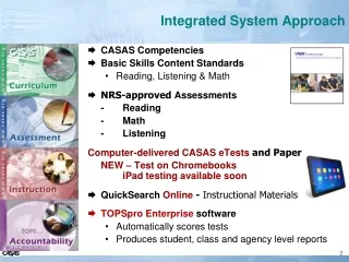
Background – Noise Models and Tools • Current Noise Models/Tools used by the FAA • Single Airport Focus • Airport Equivalency Model (AEM) – aircraft noise screening • Heliport Noise Model (HNM) – helicopter noise in the terminal area • Integrated Noise Model (INM) – high resolution aircraft noise analysis • Air Traffic Focus • Air Traffic Noise Screening Tool (ATNS) – noise screening for single aircraft type/single route analysis • NIRS Screening Tool (NST) – noise screening for multiple aircraft types/routes/airports • Noise Integrated Routing System (NIRS) – high resolution aircraft noise analysis for regional/multi-airport • All models/tools share the same noise engine developed by Volpe. NIRS/NST 3
Noise Integrated Routing System (NIRS) NIRS performs large-scale modeling and analysis of noise impacts associated with current and planned aircraft routings within a regional study area. Principal capabilities • Imports and displays track, event, population, and community data. • Enables user to easily define and track large numbers of airspace design elements. • Filters data based on user definition of study area and maximum altitude. • Enables user to specify the altitude profiles flown, including hold-downs, etc. • Applies several layers of data checking and quality control. • Provides comparison of noise impacts across alternative airspace designs. • Identifies and maps all areas of change. • Quantifies mitigation goals and identifies opportunities. • Identifies principal causes of change in noise impact. • Assembles maps, tables, and graphs for report generation. Population density and tracks in vicinity of ORD Noise exposure (DNL) NIRS/NST 4
NIRS 6.1 Feature Review • 6.1 Volpe/INM Noise engine has been integrated. • New lateral Attenuation • New military aircraft • Noise values are now rounded to the nearest 10th • FSG Enhancements • Support for profile point aircraft • Support for runway elevations • Support for other profile types • NIRS Enhancements • Added support for C weighted metrics • Windows compatibility • New Map Features • Census TIGER Data • Display multiple grids simultaneously NIRS/NST 5
NIRS Screening Tool (NST) NST performs screening of noise impacts associated with current and planned aircraft routings within a small regional study area. Principal capabilities • Based on NIRS 6.1 capabilities: • NIRS standard and custom profiles • NIRS/INM noise engine • Displays GIS data from the US. Census TIGER data. • Graphic community definition. • Graphic route definition. • Compare route changes, fleet changes or day/night changes. • Import NIRS and SDAT radar data for assistance in baseline route definition • User defined fidelity. • Generates noise exposure and noise change graphics by applying FAA criteria. Route and Community Definition Noise Change NIRS/NST 6
NST/NIRS 6.1 • Verification & Validation with INM 6.1 • User Documentation updated • NIRS User Guide • NST User Guide • Software Distribution • CDs • Secure file transfer site (https://www.metronaviation.com/nirs) NIRS/NST 7
NST Conceptual Overview NIRS/NST 8
NST – Conceptual Overview • Project Creation • Route Creation • Baseline & Alternative Routes • Route loading (day/night, aircraft type, number of ops) • Community Creation • Could be useful during route creation? • Noise Calculation • Results • Exposure • Impact • Tables/Reports NIRS/NST 9
NST – Sample Case • CMH Scenario • Baseline - Three existing right turn departure procedures off of runways 28R/L • Primary route to the north • Two secondary routes to the northeast and east • Alternative – Same three procedures with a different loading of operations • The northeast procedure (040 heading) will now have 15 day operations and 5 night operations. • The other procedures will remain the same NIRS/NST 10
NST – Startup Screen NIRS/NST 11
NST – Project Creation • Specify a study center/radius/elevation/magnetic declination • CMH • 50 nmi • 815 feet • 05W • Supporting study data • Airports/Runways (NIRS/INM Database) • Navaids/Fixes (NFDC) NIRS/NST 12
NST - Project Creation NIRS/NST 13
NST - Project Creation NIRS/NST 14
NST - Route Creation • Point and click route definition • Use supporting background map layers to show existing traffic patterns, use existing navaids or use another tool and import the routes into NST. • Baseline and Alternative Routes • One or more baseline and/or alternative routes • Routes can be arrivals, departures, and/or overflights • Arrivals begin away from the airport and terminate on the desired runway end. • Departures begin at the start of takeoff runway end and terminate away from the airport • Overflights can begin and end away from any runways • Standard or Custom profile support • Route operation loading • General ETMS aircraft categories • Specific aircraft type assignments • Day/Night assignment • Number of operations • Drawing Hints: • Snap to runway ends/navaids/existing routes. • override snap by holding down the shift-key • Zoom in and out by using keyboard short cuts • “+” zoom in centered on cursor position • “-” zoom out centered on cursor position NIRS/NST 15
NST - Route Creation • Two basic questions • How are the routes defined today and how do the routes change? (one or more) • Latitude/Longitude/Altitude/Heading/Distance • Airports/Runway/Fixes/Navaids • Standard or Custom Profiles • Level offs for arrivals • Restricted climb for departures • How are the routes used today and how would they be used in the alternative? • What type of aircraft? • What time of day did/will the operations be flown. (day/night split) • How many operations? NIRS/NST 16
NST - Route Creation • CMH Scenario • Baseline - Three existing departure routes off of runway 28R/L • Primary route to the north • Two lighter routes to the northeast and east • Alternative – Same three routes with new loading of operations • The northeast route (040 heading) will now have 15 day operations and 5 night operations. • No climb restrictions • Baseline operations • 30 day sample of ETMS data • North – average 14 light jets during the day and 2 light jets at night • Northeast – average 1 light jet during the day • East – average 1 light jet during the day and 2 light jets at night NIRS/NST 17
NST - Route Creation (Example Radar Tracks) NIRS/NST 18
NST - Route Creation NIRS/NST 19
NST - Route Creation (Baseline Routes) NIRS/NST 20
NST - Route Creation (Alternative Routes) Note: Alternative routes are on top of baseline routes. NIRS/NST 21
NST - Community Creation • Point and click community boundary definition • Use supporting background map layers to define community boundaries with NST or import community boundaries via csv file. • Community Type • Identify the community type of each community beneath the proposed change action according to its residential characteristics. Use one or more of the following four descriptions for each community: • Quiet Suburb (QS) - mostly single family, detached dwellings on lots larger than l/3 acre; few, if any, commercial or industrial sites. • Normal Suburb (NS) - mostly single family, detached dwellings on l/4 to l/3 acre lots; scattered commercial areas or apartment buildings. • Urban (U) - mostly row houses, apartment buildings, or detached dwellings on small lots; extensive commercial areas. • Noisy Urban (NU) - mostly high-rise apartments and other multifamily dwellings near, or mixed with, large commercial developments or industrial sites, but with a substantial residential population. • Grid • Grids will be generated over the community. Additionally the user is able to specify the density of the grid. (Default of .5nmi) NIRS/NST 22
NST - Community Creation NIRS/NST 23
39 049 __ ___ State County NST - Community Creation Census Bureau Tiger Website http://www.census.gov/geo/www/tiger/ Census Bureau 2006 Second Edition http://www.census.gov/geo/www/tiger/tiger2006se/tgr2006se.html NIRS/NST 24
NST – Community Creation NIRS/NST 25
NST – Community Creation NIRS/NST 26
NST – Community Creation NIRS/NST 27
NST – Community Creation NIRS/NST 28
NST – Noise Calculation NIRS/NST 29
NST – Noise Results NIRS/NST 30
NST – Noise Exposure (Baseline) NIRS/NST 31
NST – Noise Exposure (Alternative) NIRS/NST 32
Noise Reductions Noise Reductions 45dB <= Base < 60dB; Alt <= (Base 45dB <= Base < 60dB; Alt <= (Base – – 5.0dB) 5.0dB) 60dB <= Base < 65dB; Alt <= (Base 60dB <= Base < 65dB; Alt <= (Base – – 3.0dB) 3.0dB) 65dB <= Base; Alt <= (Base 65dB <= Base; Alt <= (Base – – 1.5dB) 1.5dB) Noise Increases Noise Increases 65dB <= Alt; Alt >= (Base + 1.5dB) 65dB <= Alt; Alt >= (Base + 1.5dB) 60dB <= Alt < 65dB; Alt >= (Base + 3.0dB) 60dB <= Alt < 65dB; Alt >= (Base + 3.0dB) 45dB <= Alt < 60dB; Alt >= (Base + 5.0dB) 45dB <= Alt < 60dB; Alt >= (Base + 5.0dB) NST – Noise Change (Impact) NIRS/NST 33
NIRS Conceptual Overview NIRS/NST 34
Airspace and Airport Environmental Analysis Projects Metron Aviation has been supporting such projects for over 7 years, primarily in the areas of data integration, modeling, QA, and impact analysis. • Current and Past Airspace Projects • New York/New Jersey/Philadelphia Metropolitan Airspace Redesign • Midwest Airspace Plan (STL) • Northern Utah Airspace Initiative • Omaha Airspace Redesign • Anchorage Terminal Area Redesign • Midwest AirSpace Enhancement (MASE) • CMAAP/CTAP PHL Noise Impact NIRS/NST 35
National Airspace Redesign Program: Lessons Learned • When multiple facilities are involved there is not always a common view of the airspace design (i.e., inconsistency between facilities). • All traffic patterns are not always considered in the design. Operational design leans toward major flows, where as environmental must consider all flows. • Airspace design tools are not always able to view and analyze large volumes of radar tracks and simulation data which limits their perspective on design issues. • More technical training on tools like SDAT, TARGETS, NIRS, NST, etc., is needed. • Difficult to reach closure on design « completion ». • Personnel turnover is high and structured documentation is difficult to obtain. • Environmental aspects of design are not an integral part of the design process; performed sequentially, not in parallel. NIRS/NST 36
NIRS Review • Understand NIRS capabilities. • Multiple airports, thousands of routes, 100,000 or more noise-exposure points • Use of 3-D airspace-design information • Quantifying and locating noise impacts between designs • Determining causes of noise impacts • Data quality assurance and error tracing • Review Technical Background • Noise metrics • Flight segment generation • Altitude control • Dispersion • Fleetmix • Annualization • Scoring rules • Impact graphs and maps • Identifying causes of change NIRS/NST 37
NIRS Review (Cont’d) • Review NIRS Inputs • Study area • Population data • Airport and runway data • Traffic data • Supplemental grids • Regional overlays • Review NIRS Outputs • Noise maps • Impact tables and graphs • Change maps • Change-analysis tables • Route maps • Event summary tables • Population maps • Exposure files NIRS/NST 38
NIRS Processing Overview INPUTS TRAFFIC SIMULATION SCENARIO DATA: AIRSPACE STRUCTURE AIRFIELD DEFINITION FLIGHT-RULE SUB-SCENARIO TIME FRAME FLIGHT-EVENT RUNWAYS, ROUTES, AND TIMES FOR EACH SCENARIO INPUT DATA CONVERSION AND QUALITY CONTROL POPULATION DATA EXTRACTION CENSUS DATA RELEVANT POPULATION POINTS AND OTHER LOCATIONS OF INTEREST AREA OF CONCERN CONVERTED SCENARIO DATA POPULATION, RUNWAY, AND ROUTE DATA FLIGHT SEGMENT GENERATION AIRCRAFT LOCATION AND STATE CORE NOISE EQUATIONS EXPOSURE AT SPECIFIED LOCATIONS OUTPUT DATA ASSEMBLY AND SCORING GRAPHICAL USER INTERFACE DNL DATA SCORING CRITERIA OUTPUTS NET IMPACT MEASURES FOR EACH ALTERNATIVE RELATIVE TO BASELINE, PLUS INTER-SCENARIO COMPARISONS MAP DISPLAYS: POPULATION ROUTES NOISE EXPOSURE CHANGE OF EXPOSURE NIRS/NST 39 = EXTERNAL TO NIRS
NIRS Terminology • Project • All data and computer-supported analysis associated with a given airspace-design effort. • Scenario (or design) • A baseline or alternative airspace design to be evaluated. • Plan • A specific mode of operation of a given scenario. Usually associated with weather conditions. • Traffic • A set (or sub-set) of routes and events to be modelled by NIRS for a given scenario and plan. Example: ORD daytime arrivals. • Scenario Year • The year (2000, 2005, etc.) for which traffic levels in a given scenario have been estimated. NIRS/NST 40
NIRS Terminology (Cont’d) • Flight Segment Generation • Integration of AT (route/event) and AEE (noise performance) data to calculate thrust and speed of a specific aircraft following a specific route. • Noise Modeling • Calculation of noise exposure at population centroids or other locations. • Annualization • Combining the noise exposures due to different plans according to their proportional use throughout the year. • Impact Analysis • Comparative assessment of net annual noise impacts associated with two scenarios. Based on AEE-approved rules. • Change Analysis • Determining the causes of specific impacts associated with two scenarios NIRS/NST 41
Flight Segment Generation • Objective is to calculate 3-D location, thrust, and speed information. • Information required for noise-model calculations: • Distance to observer • Thrust along segment • Speed along segment • Orientation with respect to observer (for on-ground segments) • Basic Inputs: • Aircraft type • Operation type • Trip Length • Flight Procedures • Altitude controls at specified nodes • Airport temperature • Airport altitude • Runway data END X, Y, Z, V, THR START X, Y, Z, V, THR OBSERVER NIRS/NST 42
Flight Segment Generation (Cont’d) • NIRS uses user-specified altitude control data and flight equations from the SAE 1845: • Take-off • Climb • Accelerate • Cruise/climb • Level • Descend • Land • Decelerate • Constraints: • Calculations adhere to unmodified procedures until altitude control-data requires a variation. • Altitude-control data below 3000 feet AFE is not used. Aircraft type Operation type Trip length Flight procedures Altitude controls at specified nodes Airport temperature Airport altitude Runway data FSG LOGIC USING SAE 1845 EQUATIONS Aircraft state on each segment NIRS/NST 43
Altitude Control • NIRS allows four types of altitude controls at each node on each route. • Be at or above the specified altitude • Be at the specified altitude • Be at or below the specified altitude • The altitude can have any value (no control) NIRS/NST 44
Track Dispersion • Used to model natural variation in flight paths. • NIRS aplies 2-D dispersion using center tracks and offset tracks: • Node-by-node halfwidths specify offsets to left and right of center tracks. • Track-by-track weights specify the fraction of traffic assigned to each track. • User specified data: • Any number of dispersed tracks on each route; same number to left and right. • Weight profiles for each route. • Halfwidths at each node (may be asymmetric) g h e f c d a 0.30 b 0.50 0.20 NIRS/NST 45
Scenario Scoring Methodology • EACH POPULATION CENTROID HAS TWO DNL EXPOSURE VALUES FOR: (1) BASELINE SCENARIO, (2) ALTERNATIVE SCENARIO N. • CRITERIA TO DETERMINE MINIMUM THRESHOLD OF DNL CHANGE (RELATIVE TO BASELINE DNL): • SCENARIOS ARE COMPARED IN TERMS OF POPULATION RECEIVING INCREASES OR DECREASES IN EACH EXPOSURE BAND. Baseline DNL Change in Exposure (Minimum) References < 45 dB 45 - < 50 dB 50 - < 55 dB 55 - < 60 dB 60 - < 65 dB > 65 dB - 5 dB EECP EIS, Air Traffic Noise Screening Procedure, FICON FAA Order1050.1E and FICON 5 dB 5 dB 3 dB 1.5 dB NIRS/NST 46
BASELINE DNL (dB) 0 40 45 50 55 60 65 70 Change of Exposure Map Categories 0 DEC INC TOTAL PURPLE Above 65 dB 40 BLUE TOTAL ABOVE 65 dB: Baseline = Alternative = 45 ALT DNL (dB) 50 YELLOW GREEN 55 3 dB 60 3 dB ORANGE 1.5 dB 65 1.5 dB 0 70 RED NIRS/NST 47
Impact Table, Impact Graph, and Change Map NIRS/NST 48
Identifying Causes of Change • Multiple scenarios, multiple plans, multiple traffic elements. • For a given zone of change of exposure, what traffic is the primary cause? • NIRS threads through all appropriate data to quantitatively determin primary causal factors (traffic files). • In future, NIRS will thread all the way to the level of primary casual routes and events. Future year Baseline design Future year Alternative-1 design NIRS/NST 49
Suggestions or Questions?? • Contact information Metron Aviation Inc. Mike Graham Email: graham @ metronaviation.com Office: 703-234-0764 Mobile: 571-213-6185 NIRS/NST 50