Leaf Spring Review Agenda
300 likes | 532 Vues
Leaf Spring Review Agenda. Leaf spring conditions Mockup testing Planning for the work at P5 Discussion Demonstration (if time permits and there are no communication problems). Leaf Spring Conditions. Leaf Spring Inspection/Repair Review Joe Howell Dec 19, 2007. Outline.

Leaf Spring Review Agenda
E N D
Presentation Transcript
Leaf Spring Review Agenda • Leaf spring conditions • Mockup testing • Planning for the work at P5 • Discussion • Demonstration (if time permits and there are no communication problems)
Leaf Spring Conditions Leaf Spring Inspection/Repair Review Joe Howell Dec 19, 2007
Outline • Leaf spring description • Leaf spring bond strength • Leaf spring impact on track width • Issues with leaf spring removal
Location of leaf springs • Leaf springs are located in a pocket at the ends of the forward pixel rails in the tracker • There are 8 leaf springs (4 each on +Z and –Z) 4 in top tracks and 4 in bottom tracks • The leaf springs are ~2.5 m from the face of the tracker 388 mm (~15”) Leaf Springs are located at the ends of these tracks
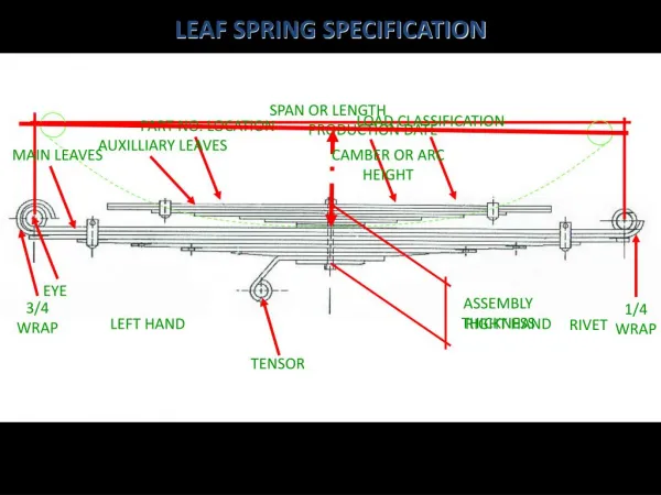
Leaf spring for front foot • The function of the leaf spring is to push the 8 mm diameter ball of the front feet of the half-cylinders against the inside face of the 9 mm track so that it is consistently registered in the same location • The leaf spring is constructed of a carbon fiber spring bonded to an aluminum angle as the carbon fiber laminate is cured. • The leaf springs apply a force of about 2.5 kg • The leaf springs are glued into the tracker rails in pockets that are machined in the rails Aluminum angle Carbon Fiber Spring Aluminum angle and carbon fiber spring are bonded as the carbon fiber laminate is cured. The aluminum to carbon fiber joint fails.
Leaf spring failure mode Carbon fiber portion of leaf spring assembly Aluminum angle of the leaf spring assembly glued to a block that simulates the rail The front foot of a service cylinder Painted black block of aluminum machined to simulate geometry of the rails in the tracker Carbon fiber to aluminum angle glue joint has failed and a gap has opened
Extended test of 4 springs • 4 leaf springs made at the same time as those installed in the tracker were mounted on a machined aluminum plate that simulated the geometry of the rail groove • The leaf springs were deflected with 8 mm diameter balls placed in a freezer (-25C). • Over a 7 month period the leaf springs were inspected monthly and allowed to warm to room temperature before returning to the freezer • 2 springs failed completely within 1 month • Only one spring is still attached but with a large gap in the original glue joint
Leaf spring installation problem • On the -Z side the gap at the springs varies from 8.3 mm to 8.0 mm. A 8 mm ball (foot on half-cylinder) will pass by all 4 springs. • On the +Z side the gap at the spring varies from 8.3 mm to less than 8.0 mm and a 8 mm ball will not pass by one of the springs These surfaces are not flush as intended
Reasons for considering removing the leaf springs • Primary Reason • The bond between the carbon fiber portion of the leaf spring and the aluminum angle is weak and is likely to fail under load sooner or later • When the leaf spring fails the half cylinder alignment will change by ~ 1 mm • If a top spring fails it may fall and hit the disks (wire bonds) • There is a small chance that any loose spring may be cause an obstruction in the tracks for the forward pixel or barrel • Any future work on the leaf springs after the beam pipe is installed and the detector has operated will be very difficult. • Secondary Reason • The leaf springs were installed in a way that obstructs most of the clearance between the ball of the half-cylinder front foot and the anchor point of the spring. (One spring has no clearance and the ball cannot pass by the spring anchor point) • With only 0.3 mm maximum clearance, reinforcing the leaf spring attachment is not a reliable option • The carbon fiber leaf is ~ 1mm thick and removing that portion should allow the front foot to pass at the one location where it is now obstructed • If we knew the leaf would not fall off we would most likely grind one side of the ball on the one front foot at the obstructed location
Issues with removing the leaf springs • Access and visibility or limited • The leaf springs are located ~2.5 m from the face of the tracker • The top and bottom rails are only 38.8 cm apart • The rails can not support large loads like the weight of a person • Very limited natural light and low contrast with carbon rails • Features on the scale of 1 mm or less in size may be important to see • The bond strength of all of the glue attachments is not known • The bond of the carbon fiber leaf to the aluminum angle is not very strong • If this were the only attachment of the leaf spring then removal would be relatively easy • The bond of the aluminum angle to the rail is much stronger. (We would not try to remove the aluminum angle) • If the glue used to bond the aluminum angle to the rail has squeezed on to the carbon fiber leaf the attachment of the carbon fiber leaf may be significantly stronger • Logistics are a problem • Very limited access to the tracker • There is no time to iterate while working on the tracker, need to be prepared for all contingencies
Leaf Spring Strategy • The bond strength of all of the glue attachments is not known • The bond of the carbon fiber leaf to the aluminum angle is weak but … • If the glue used to bond the aluminum angle to the rail has squeezed on to the carbon fiber leaf the attachment of the carbon fiber leaf may be significantly stronger • Need to inspect the glue attachment to try to determine if glue has squeezed on to the carbon fiber leaf making it hard to remove • If glue bonding the aluminum angle in place has not squeezed on to the carbon fiber leaf then removal of the leaf should be relatively easy • A leaf spring that would be hard to remove does not need to be removed • We would not try to remove the aluminum angle
Mockup Testing Leaf Spring Inspection/Repair Review Joe Howell Dec 19, 2007
Outline • Mockup Description • Camera setup and inspection cart • Leaf spring photography • Leaf spring removal testing • Additional work
Tracker Inner bore mockup • 2 Back PVC sheets with rail grooves • Most restrictive area is the center support barrel • Black felt cloth used to block light Removable block for mounting leaf springs Adding beam pipe support arms now Black PVC sheets with track grooves machined
Center support barrel Aluminum block to simulate beam pipe support pulley The tracker mockup (with cart inside) Photo of tracker inner bore taken July07
Inspection Cart • Cart rolls on rubber wheels and is pushed in by hand • Cart holds camera and tool support • Many wires are bundled on the cart • Cart has clearance to pass over beam pipe support
Still Camera Setup • 12Mp still camera controlled by computer through USB cable • Motorized camera pan and tilt mount • LED light array • Several wires • USB cables for camera and mount • DC power cable for camera • LED wires Camera Motorized camera mount LEDs Leaf springs
Digital zoom of still photo • Epoxy (Araldite 2011) used to bond springs into tracks is visible • Various combinations of LED lights, camera flash and viewing angles are used to inspect for additional epoxy on springs
Removal tool setup • 2.5 M long carbon fiber rod with tools on end • Simple tool used to peel carbon fiber leaf from aluminum angle by wedging a pin in the gap between leaf and the side of groove • Removing an upper leaf is moderately more difficult than a lower leaf spring. • A pulley is used to support the rod near the working end for upper spring removal • Work observed with camera “viewfinder” End of long rod for spring removal tool (tool will be mounted on the end of rod) Pulley to support end of rod
Notes on leaf detachment • Three leaf springs detached so far have peeled away from aluminum as expected • One spring tested was in the upper position and was not significantly more difficult • Force to peel the leaf away has a significant variation across the 3 samples. • This is a qualitative judgment. The force exceeded the 2kg capacity of the force gauge in hand • The force required for the initial peel has been less than the force required for final separation. • The aluminum angle has not separated • No observable “debris” from glue joint • 5 more springs made at the same time as the original installed leaf springs are available to test.
Additional Work • Complete LED holding clamps • Make additional rods and tools ends for sweeping or gripping loose leaves • Add polyethylenetape to metal parts of tools where possible and radius all edges to prevent scrapping • Complete testing of 5 remaining springs and practice with some additional new springs • Check out vacuum cleaning and wet wiping of any debris • Add a USB extender for motorized mount. (It is at the cable length limit without much slack between the tracker and the laptop • Replace English unit frame cart with Bosch metric (30 mm) • Measure time required for setup and inspection and removal operations • Check out power conversion equipment • Consider backups for critical items (camera, motorized mount)
Planning for work at P5 Leaf Spring Inspection/Repair Review Joe Howell Dec 19, 2007
Topics • Mockup features (anything missing ?) • Support platform • Time required • Training • Schedule (when ?)
Support platform • Need additional information on the Surkov frame and the extensions. • Need to understand how close to the tracker face one can stand and the distance a support platform is from the beam centerline. • Is outlet power available near the tracker ? ? ?
Time Required • Leaf Spring Inspection Estimate • 2 hours of setup (2 hours on first side and 1 hour on the other side) • 2 hours of time to photograph per side • It could be possible to photograph all springs from one side if there is a significant scheduling advantage • Ideally there could be at least a one to two day gap after photographing the springs to reach a conclusion on whether to remove them or not • Leaf Spring Removal Estimate • 1 hour of setup per side • 2 to 4 hours of time for removal per side
Discussion • Training required ? • Scheduling the task • Next steps ?