Understanding Signals: From Transmission to Modulation in Telecommunications
330 likes | 447 Vues
This material delves into the fundamental concepts of signals as time-varying events that convey information from a transmitter to a receiver. It explores the distinctions between time and frequency domains, the nature of periodic signals, and the significance of bandwidth in communication systems. Topics such as Frequency Division Multiplexing (FDM), modulation techniques including AM and QPSK, and the role of filters in signal processing are discussed. The analysis highlights how signal representations impact data transmission efficiency and telecommunications applications.

Understanding Signals: From Transmission to Modulation in Telecommunications
E N D
Presentation Transcript
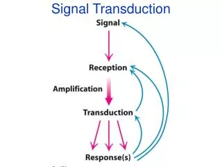
signal • A signal is a time-varying event that conveys information from a source to a destination (more accurately, from a transmitter to a receiver). • physical representation of data • Frequency domain vs. time domain
signal • Signal can be composed of a number of periodic signals • parameters of periodic signals: period T, frequency f=1/T, amplitude A, phase shift • E.g., sinewave is expressed as s(t) = At sin(2 ft t + t)
Time and Frequency Analysis are Really Looking at the Signal from Different Points of View
signal • Different representations of signals • amplitude (amplitude domain) • frequency spectrum (frequency domain) • phase state diagram (amplitude M and phase in polar coordinates) Q = M sin A [V] A [V] t[s] I= M cos f [Hz]
signal By Fourier analysis f=1/T
Low pass filter Band pass filter
Baseband signal Bandpass signal
MAKING SENSE OF THE TIME/FREQUENCY EQUIVALENCE OF SIGNALS • We do this math to get insights regarding the nature and processing of signals for telecommunications purposes. • All facilities (definition: communications links) have limited bandwidth: usually a low pass or band pass characteristic. • The frequency analysis allows us to understand how limiting the frequencies allowed affect the signals as they travel through the facility. • Limiting the bandwidth reduces the sharpness of time transitions and the number of changes possible per second due to distortions of shape of signals. Therefore, digital data rates are reduced.
Frequency Division Multiplexing (FDM) • Concept is to convert the energy of signals to occupy different parts of the frequency domain so that many signals can share a “facility” (communications link). • Process to move the energy within the frequency domain is called modulation. • Modulation is employed often so that many signals can be radiated (via wireless transmission), share wires, or for other transmission advantages. More on that later. • The process of sharing facilities by different signals is called multiplexing. We’ll talk about other multiplexing schemes later. • When the sharing method is by means of such frequency conversions, it’s called Frequency Division Multiplexing. • Band pass filters are used to separate out each modulated signal. • Demodulation schemes are used to regenerate each individual signal and restore it to its original spectrum and time domain signals.
AM Demodulation of AM can be just a matter of connecting the peak voltages of the modulated waveform and using a simple RC filter to “smooth” out the signal.
QPSK Modulation • 4 Symbols, 2 bits/symbol • Signal shifts between the phase states are separated by 90 degrees • Since the two carriers, cos(ct) and sin(ct) are orthogonal they do not interfere with each other • Any symbol can transition to any other symbol
OQPSK Modulation Transitions for a QPSK modulated signal Transitions for a OQPSK modulated signal • Variation of QPSK • Q channel is delayed by a ½ bit interval from I channel • I and Q channel signals transition at different times • Range of phase transitions is from 0-90 degrees • This eliminates the 180 degree phase shift so an OQPSK signal never goes through a zero • In non-linear amplification, a zero causes regeneration of sidelobes and spectral spreading in the signal • Thus, OQPSK signals yield a more efficient amplification process
QPSK OQPSK