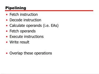
Pipelining
Pipelining. Hakim Weatherspoon CS 3410 Computer Science Cornell University. [Weatherspoon, Bala , Bracy , McKee, and Sirer ]. Review: Single Cycle Processor. memory. register file. inst. alu. +4. +4. addr. =?. PC. d in. d out. control. cmp. offset. memory. new pc. target.

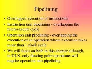
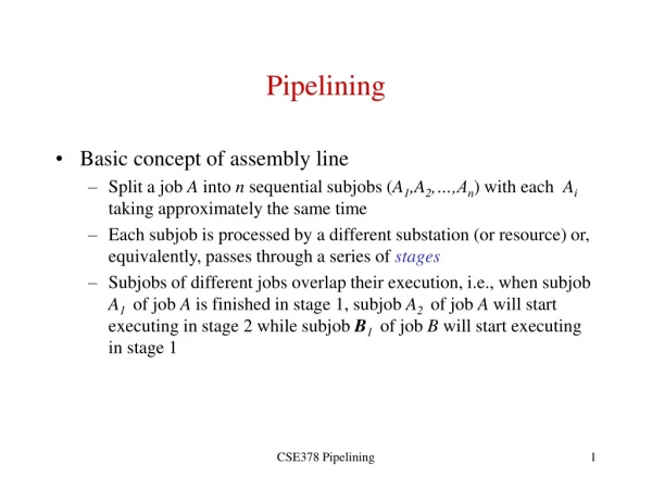
Pipelining
E N D
Presentation Transcript
Pipelining Hakim Weatherspoon CS 3410 Computer Science Cornell University [Weatherspoon, Bala, Bracy, McKee, and Sirer]
Review: Single Cycle Processor memory registerfile inst alu +4 +4 addr =? PC din dout control cmp offset memory new pc target imm extend
Review: Single Cycle Processor • Advantages • Single cycle per instruction make logic and clock simple • Disadvantages • Since instructions take different time to finish, memory and functional unit are not efficiently utilized • Cycle time is the longest delay • Load instruction • Best possible CPI is 1 (actually < 1 w parallelism) • However, lower MIPS and longer clock period (lower clock frequency); hence, lower performance
Review: Multi Cycle Processor • Advantages • Better MIPS and smaller clock period (higher clock frequency) • Hence, better performance than Single Cycle processor • Disadvantages • Higher CPI than single cycle processor • Pipelining: Want better Performance • want small CPI (close to 1) with high MIPS and short clock period (high clock frequency)
Improving Performance • Parallelism • Pipelining • Both!
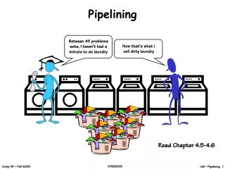
The Kids Alice Bob They don’t always get along…
The Materials Saw Drill Glue Paint
The Instructions N pieces, each built following same sequence: Saw Drill Glue Paint
Design 1: Sequential Schedule Alice owns the room Bob can enter when Alice is finished Repeat for remaining tasks No possibility for conflicts
Sequential Performance time1 2 3 4 5 6 7 8 … Elapsed Time for Alice: 4 Elapsed Time for Bob: 4 Total elapsed time: 4*N Can we do better? Latency: Throughput: Concurrency: CPI =
Design 2: Pipelined Design Partition room into stagesof apipeline Dave Carol Bob Alice One person owns a stage at a time 4 stages 4 people working simultaneously Everyone moves right in lockstep
Pipelined Performance time1 2 3 4 5 6 7… Latency: Throughput: Concurrency: CPI =
Pipelined Performance Time 1 2 3 4 5 6 7 8 9 10 What if drilling takes twice as long, but gluing and paint take ½ as long? Latency: Throughput: CPI =
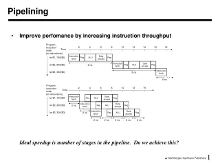
Lessons • Principle: • Throughput increased by parallel execution • Balanced pipeline very important • Else slowest stage dominates performance • Pipelining: • Identify pipeline stages • Isolate stages from each other • Resolve pipeline hazards(next lecture)
Single Cycle Pipelining Single-cycle insn0.fetch, dec, exec insn1.fetch, dec, exec Pipelined insn0.fetch insn0.dec insn0.exec insn1.fetch insn1.dec insn1.exec
Agenda • 5-stage Pipeline • Implementation • Working Example • Hazards • Structural • Data Hazards • Control Hazards
Review: Single Cycle Processor memory registerfile inst alu +4 +4 addr =? PC din dout control cmp offset memory new pc target imm extend
Pipelined Processor memory registerfile inst alu +4 addr PC din dout control memory computejump/branchtargets new pc imm extend Decode Execute Fetch Memory WB
Pipelined Processor memory registerfile A alu D D B +4 addr PC din dout B M inst control memory computejump/branchtargets newpc extend imm Write-Back InstructionDecode InstructionFetch Memory ctrl ctrl ctrl Execute IF/ID ID/EX EX/MEM MEM/WB
Time Graphs Cycle add IF ID EX MEM WB nand IF ID EX MEM WB IF ID EX MEM WB lw IF ID EX MEM WB add sw IF ID EX MEM WB Latency: Throughput: Concurrency: Latency: Throughput: CPI =
Principles of Pipelined Implementation • Break datapath into multiple cycles (here 5) • Parallel execution increases throughput • Balanced pipeline very important • Slowest stage determines clock rate • Imbalance kills performance • Add pipeline registers (flip-flops) for isolation • Each stage begins by reading values from latch • Each stage ends by writing values to latch • Resolve hazards
Pipelined Processor memory registerfile A alu D D B +4 addr PC din dout B M inst control memory computejump/branchtargets newpc extend imm Write-Back InstructionDecode InstructionFetch Memory ctrl ctrl ctrl Execute IF/ID ID/EX EX/MEM MEM/WB
Instruction Fetch (IF) Stage 1: Instruction Fetch Fetch a new instruction every cycle • Current PC is index to instruction memory • Increment the PC at end of cycle (assume no branches for now) Write values of interest to pipeline register (IF/ID) • Instruction bits (for later decoding) • PC+4 (for later computing branch targets)
Instruction Fetch (IF) instructionmemory addr mc +4 PC newpc
Decode • Stage 2: Instruction Decode • On every cycle: • Read IF/ID pipeline register to get instruction bits • Decode instruction, generate control signals • Read from register file • Write values of interest to pipeline register (ID/EX) • Control information, Rd index, immediates, offsets, … • Contents of Ra, Rb • PC+4 (for computing branch targets later)
Decode registerfile WE A A Rd D B B Rb Ra inst Stage 1: Instruction Fetch Rest of pipeline imm PC+4 PC+4 ctrl IF/ID ID/EX
Execute (EX) • Stage 3: Execute • On every cycle: • Read ID/EX pipeline register to get values and control bits • Perform ALU operation • Compute targets (PC+4+offset, etc.) in case this is a branch • Decide if jump/branch should be taken • Write values of interest to pipeline register (EX/MEM) • Control information, Rd index, … • Result of ALU operation • Value in case this is a memory store instruction
Execute (EX) A D alu B imm B Stage 2: Instruction Decode Rest of pipeline target PC+4 ctrl ctrl ID/EX EX/MEM
MEM • Stage 4: Memory • On every cycle: • Read EX/MEM pipeline register to get values and control bits • Perform memory load/store if needed • address is ALU result • Write values of interest to pipeline register (MEM/WB) • Control information, Rd index, … • Result of memory operation • Pass result of ALU operation
MEM D D addr B M din dout Stage 3: Execute Rest of pipeline memory target mc ctrl ctrl EX/MEM MEM/WB
WB • Stage 5: Write-back • On every cycle: • Read MEM/WB pipeline register to get values and control bits • Select value and write to register file
WB result D M Stage 4: Memory ctrl MEM/WB
Putting it all together instmem A A Rd D D D B B inst addr Rb Ra B M dout din imm +4 mem PC+4 PC+4 PC Rd Rd Rd Rt OP OP OP ID/EX EX/MEM MEM/WB IF/ID
Takeaway • Pipelining is a powerful technique to mask latencies and increase throughput • Logically, instructions execute one at a time • Physically, instructions execute in parallel • Instruction level parallelism • Abstraction promotes decoupling • Interface (ISA) vs. implementation (Pipeline)
RISC-V is designed for pipelining • Instructions same length • 32 bits, easy to fetch and then decode • 4 types of instruction formats • Easy to route bits between stages • Can read a register source before even knowing what the instruction is • Memory access through lw and sw only • Access memory after ALU
Agenda 5-stage Pipeline • Implementation • Working Example • Hazards • Structural • Data Hazards • Control Hazards
Example: Sample Code (Simple) add x3 x1, x2 nand x6 x4, x5 lw x4 x2, 20add x5 x2, x5sw x7 x3, 12 Assume 8-register machine
M U X 4 target + PC+4 PC+4 0 x0 x1 regA ALU result Inst mem x2 Register file regB valA M U X PC Data mem instruction x3 A L U ALU result mdata x4 valB x5 x6 M U X data x7 imm dest extend valB Bits 7-11 Rd dest dest Bits 15-19 M U X Rt Bits 0-6 op op op ID/EX EX/MEM MEM/WB IF/ID
At time 1, Fetch add x3 x1 x2 A L U Example: Start State @ Cycle 0 M U X 4 0 + 0 0 0 x0 0 36 x1 regA 0 Add Nand Lw Add sw 9 x2 Register file regB 0 M U X PC Data mem nop 12 x3 0 0 18 x4 4 0 7 0 x5 41 x6 M U X data 22 x7 0 dest extend 0 Initial State Bits 7-11 0 0 0 Bits 15-19 M U X 0 Bits 0-6 nop nop nop ID/EX EX/MEM MEM/WB IF/ID
Agenda 5-stage Pipeline • Implementation • Working Example • Hazards • Structural • Data Hazards • Control Hazards
Hazards Correctness problems associated w/ processor design • Structural hazards Same resource needed for different purposes at the same time (Possible: ALU, Register File, Memory) • Data hazards Instruction output needed before it’s available • Control hazards Next instruction PC unknown at time of Fetch
Dependences and Hazards Dependence: relationship between two insns • Data: two insns use same storage location • Control:1 insn affects whether another executes at all • Not a bad thing, programs would be boring otherwise • Enforced by making older insn go before younger one • Happens naturally in single-/multi-cycle designs • But not in a pipeline Hazard: dependence & possibility of wrong insn order • Effects of wrong insn order cannot be externally visible • Hazards are a bad thing: most solutions either complicate the hardware or reduce performance
Where are the Data Hazards? Clock cycle 1 2 3 4 5 6 7 8 9 time add x3, x1, x2 subx5, x3, x4 lw x6, x3, 4 orx5, x3, x5 swx6, x3, 12
Data Hazards • register file reads occur in stage 2 (ID) • register file writes occur in stage 5 (WB) • next instructions may read values about to be written i.e. add x3, x1, x2 sub x5, x3, x4 How to detect?
Detecting Data Hazards instmem A A Rd D D D B B inst addr Rb Ra B M dout din imm +4 mem PC+4 PC+4 PC Rd Rd IF/ID.Rs1 ≠ 0 && (IF/ID.Rs1==ID/Ex.Rd IF/ID.Rs1==Ex/M.Rd IF/ID.Rs1==M/W.Rd) Rd Rt OP OP OP • add x3, x1, x2 sub x5,x3,x4 ID/EX EX/MEM MEM/WB IF/ID repeat for Rs2
Data Hazards Data Hazards • register file reads occur in stage 2 (ID) • register file writes occur in stage 5 (WB) • next instructions may read values about to be written How to detect? Logic in ID stage: stall = (IF/ID.Rs1 != 0 && (IF/ID.Rs1 == ID/EX.Rd || IF/ID.Rs1 == EX/M.Rd || IF/ID.Rs1 == M/WB.Rd)) || (same for Rs2)
Detecting Data Hazards instmem A A Rd D D D B B inst addr Rb Ra B M dout din imm +4 mem detecthazard PC+4 PC+4 PC Rd Rd Rd Rt OP OP OP ID/EX EX/MEM MEM/WB IF/ID