Understanding DLX Pipeline Architecture: Instruction Overlap and Execution Efficiency
This chapter focuses on pipelining concepts in computer architecture, highlighting both instruction and operation unit pipelining to enhance performance. We define essential terminology such as pipe stages, throughput, and machine cycles, and explore the DLX pipeline stages, including instruction fetch, decode, execution, memory access, and writeback. Through examining various operations, including ALU functions and memory references, we analyze how pipelining affects overall performance, branch penalties, and ways to optimize cycles per instruction (CPI). Challenges related to simultaneous instruction processing and hardware solutions, such as latches and multiplexors, are also discussed.

Understanding DLX Pipeline Architecture: Instruction Overlap and Execution Efficiency
E N D
Presentation Transcript
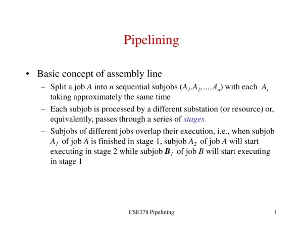
Pipelining • Overlapped execution of instructions • Instruction unit pipelining - overlapping the fetch-execute cycle • Operation unit pipelining - overlapping the execution of an operation whose execution takes more than 1 clock cycle • We will focus on both in this chapter although, in DLX, only floating point operations will require operation unit pipelining
Terminology • Pipe Stage - also a pipe segment, each step in a pipeline • Throughput - how often an instruction exits the pipeline • Machine cycle - time to move through 1 pipe stage • Stall - a situation in which a pipe stage requires more than 1 machine cycle to complete -- this freezes the pipe until that stage is done • Time per instruction on a pipelined computer: • TPI = TPI unpipelined / number of pipe stages
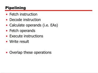
DLX Pipeline • IF - instruction fetch cycle • Send out PC • Fetch instruction from memory into IR • Set NPC = PC 4 • ID - instruction decode/register fetch cycle • Decode instruction in IR • Access register file to read registers for operands • Place operands into two temporary registers (A and B) • Lower 16 bits of IR stored in Imm temporary register (for next cycle)
DLX Pipeline continued • EX - execution/effective address cycle • ALU performs operation on A and B • Four possible functions: • memory reference: ALU adds A and Imm for effective address (for load or store operation)* • register-register ALU operation: A func B* • register-immediate operation: A op Imm* • branch: branch target = NPC + Imm; condition is A op 0 (op is == or !=) • * - Result of function placed in ALUOutput temporary register
DLX Pipeline continued • MEM - Memory access/branch completion cycle • only active instructions for this cycle are loads, stores and branches • Memory reference - if load, datum loaded into LMD temporary register, if store, datum from B is stored at location in ALUOutput • Branch - if (cond) then change PC = ALUOutput else PC = NPC (PC + 4)
DLX Pipeline continued • WB - writeback cycle • Used to store result of ALU or Load operation • Register-register ALU or Register-immediate operation: store in destination register value of ALUOutput • Load instruction: store in destination register the value currently in LMD • See figure 3.1, page 130 for all 5 stages including data flow and circuits
Effectiveness of DLX pipeline • Branches and Stores require four cycles (first 4 stages) and all other instructions require five cycles • Assuming branch frequency of 12%, store of 5%, overall CPI for DLX = 4.83 • Can improve CPI by completing ALU operations in MEM cycle (since output is already known) • Assuming ALU instruction frequency of 47%, overall CPI improves to 4.35 or a speedup of 4.82/4.35=1.1 • Other means of decreasing CPI will probably require increasing the clock cycle time, not worth it
Other Comments on DLX Pipe • Requires at least 2 ALUs - one to increment the PC (IF) and one for ALU operations and computing effective addresses (EX) • Requires several temporary registers (IR, A, B, Imm, NPC, ALUOutput, LMD) • Multiplexors used to select what to do after a condition is evaluated and whether a computed value is to be used later in A or B
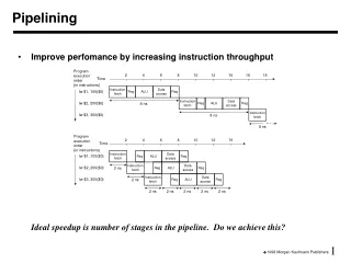
Basic Usage of the DLX Pipe • Instruction # 1 2 3 4 5 6 7 • Instruction 1 IF ID EX Mem WB • Instruction 2 IF ID EX Mem WB • Instruction 3 IF ID EX Mem WB • Instruction 4 IF ID EX Mem • Instruction 5 IF ID EX • Instruction 6 IF ID • Instruction 7 IF • See figures 3.2 and 3.3 (pages 132-133)
Problems • The PC can be modified during the IF stage and the MEM stage. Two instructions could attempt to alter the PC at the same clock cycle! • Every clock cycle there is a need for two memory accesses - instruction fetch (IF) and a data fetch (ID). • Every clock cycle a register may be accessed twice (ID and WB stages). • We need ways to handle all of these conflicts. The fetches from memory can be handled by 2 caches and 2 buses. What about the others?
Additional Hardware - Latches • In order to properly synchronize the DLX pipeline, we need a clock controlled mechanism between stages -- latches • This allows each stage to complete its duties before passing info to the next stage • Latches can stop data flow in the case of a stall • Latches denoted as A/B for latch between stage A and B (e.g., IF/ID, ID/EX) • See Figure 3.4, page 134
Detailed Events of the Pipeline • See Figure 3.5, page 136 • IF - instruction fetch • IR gets the instruction from memory as pointed to by the PC • NPC (a temporary register stored in the IF/ID latches) and PC are updated to be PC + 4 or the value stored in the ALUOutput in the EX/MEM latches • The decision as to whether the NPC and PC are PC+4 or ALUOutput is decided by the condition stored in EX/MEM (set during previous EX operation)
Events continued • ID Stage: • Register A gets value stored in first operand register (as denoted by bits 6..10 in IR) • Register B gets value stored in second operand (bits 11..15 in IR) • NPC gets value from IF/ID.NPC through latch • IR gets value from IF/ID.IR through latch • Imm gets low order 16 bits from IR (the immediate data) with bit 16 duplicated 16 more times to give Imm proper sign (in 2’s complement)
Events continued • EX stage: • IR gets ID/EX.IR from latches • ALUOutput stores result of operation • A func B or A op Imm (if ALU operation) (decision made by multiplexor based on IR bits) • A + Imm (if load/store operation) • NPC + Imm (if branch) • Condition set • to 0 (if ALU, load or store operation) • to A op 0 (if branch) where op is specified in IR as = or != • Register B gets ID/EX.B from latches (if load/store)
Events concluded • MEM Stage: • IR gets EX/MEM.IR from latches • ALUOutput gets EX/MEM.ALUOutput (if ALU operation) • LMD (loaded memory data register) gets ALUOutput or ALUOutput gets value of register B (if load/store) (decision made by multiplexor based on bits in IR) • WB Stage: • Destination register (as specified in IR) gets ALUOutput (if ALU operation) or LMD (if load/store)
DLX Performance Issues • Pipelines lower total execution time even though no single instruction is executed any faster • In fact, pipelines have slowdowns caused by: • pipeline latency • imbalances among pipeline stages (clock cycle may be as fast as the slowest pipeline stage) • pipeline overhead (e.g., latches, register setup time)
Example - pipelined vs. unpipelined machine • Unpipelined machine has 10ns clock cycle • Operations: • frequency: 40% ALU, 20% branches, 40% load/store • speed: 4 cycles ALU, branch, 5 cycles load/store • Pipelined machine has 10ns clock cycle plus 1ns due to clock skew, setup time, etc… • How much speedup would we achieve with pipelined machine?
Solution • Unpipelined computer: • Average instruction execution time = clock cycle * average CPI = 10 ns * (40%*4 + 20%*4 + 40% * 5) = 44 ns • Pipelined computer: • Average instruction execution time = 11 ns • Speedup from pipelining: • 44 ns/11 ns = 4 times
Another Example • Assume that our base machine has a CPI of 1 (it will have a longer clock cycle than in previous example) • Pipelining will enable a shorter clock cycle since each stage will contain a part of the total execution • Use the same datapath as the pipelined machine but remove latches to make it unpipelined • Assume for unpipelined machine execution times of 10 ns, 8 ns, 10 ns, 10 ns and 7 ns for each portion of the datapath. • Assume pipelined machine has 1 ns overhead.
Solution • What is the speedup of the pipelined version? • Unpipelined: • Average instruction execution time = 10 ns + 8 ns + 10 ns + 10 ns + 7 ns = 45 ns • Pipelined: • 10 ns is longest clock cycle + 1 ns for overhead = 11 ns • Speedup: • 45 ns / 11 ns = 4.1 times
Impact of Latches • Latches have a significant impact on clock speed • Designers look for latches with the highest possible clock rate • Earle latch (invented in 1965) have 3 properties that make them useful for pipelined machines: • relatively insensitive to clock skew • delay through latch is a constant two-gate delay • two levels of logic can be applied to the latch allowing for overlapped logic on the latch without increasing delay
Pipeline Hazards • Anything that can prevent the next instruction in the instruction stream from starting execution in a pipe • These reduce the performance of the pipeline which in turn affects the pipe’s ideal speedup • Three types of hazards: • Structural Hazards - resource conflicts • Data Hazards - data conflicts • Control Hazards - changes to the PC
Stall • The term applied to what happens to the pipeline because of hazards • A stall causes each stage of the pipeline prior to the hazard to freeze execution, not allowing them to send their results to the next stage or start again on the new results from the previous stage • Instructions later in the pipe than the hazard (I.e. those started earlier in time) are not affected and so are not stalled • There are hardware and software mechanisms to avoid hazards and reduce or eliminate stalls
Performance of a pipe with stalls • Speedup from pipelining = avg instr time unp / avg instr time p = CPIunp/CPIp * clockcycle unp/clockcycle p • p = pipelined machine, unp = unpipelined machine • Ideal CPIp = 1, so CPI p = 1+pipeline stalls per instr • Ignoring overhead and unevenness of pipeline stages, then the cycle time of both machines can be equal and so clockcycle unp/clockcycle p = 1 • Speedup = CPI unp / 1+pipeline stalls = Pipeline depth/1+pipeline stalls • With 0 stalls, we see that speedup = pipeline depth
Structural Hazards • Because of overlapped instructions, there may be a need for one piece of hardware to function on two separate instructions simultaneously -- this is a structural hazard • May arise if a functional unit is not pipelined • Consider an integer multiplier which takes more than 1 clock cycle to complete, two or more integer multiplication instructions may be in the pipeline • The pipeline must stall those instructions in the pipe requiring the same functional unit (it may also stall all other succeeding instructions) • This will raise ideal CPI > 1
Other causes of structural hazards • If a machine has a shared single-memory pipeline (I.e. memory/bus/cache must share between instruction and data fetches) • A machine may have only 1 register-file write port but on occasion, may require 2 writes in a clock cycle (from 2 different stages) • Adder/incrementer - may be needed in an ALU operation and also used each cycle to increment the PC
Results of a Structural Hazard • As shown in figures 3.6 and 3.7 on pages 142 and 143, there is a stall because of a hazard • In this case, the hazard arises because of two simultaneous memory accesses from two separate stages in the pipeline • The second memory access is stalled (see figure 3.7, stall “bubbles” are inserted) • Result of the stall instruction 3 must start 1 clock cycle later, causing overall execution time to increase by 1 clock cycle (see fig 3.8, p. 144)
Example • Computer 1 has a pipeline with the structural hazard caused by data and instruction references simultaneously, but has a clock rate 1.05 higher than Computer 2 which does not have the structural hazard • Suppose 40% of all instructions have data references • The ideal CPI of both machines is 1 • Which machine is faster?
Solution • Average instruction time = CPI * clock cycle time • Machine 1 has stalls and so its CPI = 1 + % of instr’s with stalls * stall = 1 + 40% * 1 = 1.4 • Since machine 1 has a clock rate of 1.05 times faster than machine 2 which has no stalls, we have avg instr time = 1.4 * clock cycle ideal/ 1.05 = 1.3 clock cycle ideal • Or, machine 2 (without structural hazards) is 1.3 times faster than machine 1
Why have structural hazards? • In the previous example, we could enhance machine 1 to have two caches and buses but this will be more expensive and will also increase the number of pins required on the chip (or provide on-chip cache which takes up real estate) • In some cases, it doesn’t make sense to duplicate functional units (such as having two or more floating point division units) • In some cases (like two caches) it does • It depends on how often the hazard might arise
Example • Assume DLX has a 5 clock cycle floating point multiply, but not pipelined (so that two floating point mults will cause a structural hazard) • Will this hazard have a large or small impact on the mdljdp2 benchmark? (assume floating point multiplications are uniform across the program) • From chapter 2, we note that mdljdp2 has 14% frequency of these floating point mults.
Solution • Since our floating point multiplier requires 5 clock cycles, a structural hazard will only occur if a second multiply occurs before the first terminates, so they must be within 5 instructions of each other • Assuming a uniform distribution, this will not arise and so a pipelined multiplication unit will not be utilized well enough to make it worth while • In the worst case (multiplies are clustered together with no intervening instructions), each multiply will take 6 cycles (1 normal, 5 stalls), changing the base CPI from 1 to 1.7
Data Hazards • These hazards occur because of dependencies of operands within the instructions so that one operand is not yet available when needed by another instruction in the pipeline • ADD R1, R2, R3 SUB R4, R1, R5 AND R6, R1, R7 OR R8, R1, R9 XOR R10, R1, R11 • Notice that R1 is produced in the first instruction and used as an operand in all the remaining instructions.
Result from this example • See figure 3.9, p. 147 • R1 is not produced until the WB stage of the first instruction in spite of being needed in earlier clock cycles of other instructions • Unless caught, the SUB and AND instructions will read the wrong value of R1. • Will the OR instruction read the correct value of R1? We can force register reads to occur after register writes allowing the OR instruction to receive the correct value of R1 • Only XOR is definitely ok.
To Resolve Data Hazards • Forwarding (also called bypassing or short-circuiting) will allow a stage to send a computed value onto the locations in the pipeline that are waiting for it • Performed by hardware connected to the latches • This does not need to be limited to WB & ID stages • ALU result from EX/MEM register fed back to ALU input latches • MEM/WB register fed back to ALU input latches • See fig 3.10 p. 149 for how these solutions will resolve the problems of the given example without stalls!
Another Example • ADD R1, R2, R3 LW R4, 0(R1) SW 12(R1), R4 • Need to forward value of R1 after computed in EX stage to next instruction’s EX phase to be used to calculate an effective address • Need to forward value stored in R4, after it is loaded from cache in its MEM stage to next instruction’s EX phase to be used to calculate an effective address • See figure 3.11, page 150
Data Hazard Classification • Data Hazards occur when dependencies arise between any pair of instructions which are close enough in the pipeline to cause overlap • This may happen if a pair of instructions share the same register or memory location. The 3 forms of data hazards are: • RAW - read after write • WAW - write after write • WAR - right after read • Note that RAR (read after read) is not a hazard since the value is not being changed
RAW hazards • Read after write • Instruction j tries to read a source before instruction i writes it so j gets the old value • Most common form of data hazard • Overcome by using forwarding, as soon as instruction i has computed value, it is forwarded to the proper stage for instruction j to use it • ADD R1, R2, R3 SUB R4, R1, R5 {SUB instruction tries to read R1 before it is written by ADD instruction}
WAW hazards • Write after write • Instruction j tries to write an operand to a location before it has been written to by instruction i. The writes are performed in the wrong order • This type of hazard is only possible in a pipeline where writes may occur in more than one stage or instructions can complete out of order • Example in a pipeline which requires two stages or cycles for a memory access: • LW R1, 0(R2) IF ID EX M1 M2 WB ADD R1, R2, R3 IF ID EX WB
WAR hazard • Write after read • Instruction j tries to write to a destination before instruction i tries to read the value • This cannot happen in DLX because all reads are in the ID stage and all writes in the WB stage • This could happen in a pipeline where there are multiple stages that a read or write can occur but is rare since most pipelines have reads occurring prior to writes
Why data hazards require stalls • If a value becomes available in instruction i at stage j, then we can forward this value to instruction i+1 at stage j-1, or instruction i+2 at stage j-2, etc… • What if instruction i+2 needs the datum at stage j-1? Obviously, the value is not ready yet and so instruction j must stall • Not all data hazards cause stalls, but some do
DLX Data Hazard Example • Consider the following sequence: • LW R1, 0(R2) SUB R4, R1, R5 AND R6, R1, R7 OR R8, R1, R9 • See figure 3.12, page 153 for datapath • LW instruction computes the effective address in EX stage and fetches it in MEM stage, so cannot forward R1 until the end of the MEM stage • The SUB instruction uses R1 at the beginning of its EX stage which takes place at the same time as LW’s MEM
Example continued • Therefore, the SUB instruction must stall prior to its EX stage in order for LW to forward the value in time • Notice that neither AND nor OR must be stalled because R1 can be forwarded to them prior to those instructions needing R1 • However, since SUB stalls, so do AND and OR • The result of these stalls is shown in figures 3.13 and 3.14 (p. 154)
DLX Data Hazards • In DLX, since reads occur prior to writes, there are no WAR hazards and since all writes occur in single stages, there are no WAW hazards • We must deal with RAW hazards (as shown in the previous example) • To control stalls due to data hazards, we need to add hardware called pipeline interlocks to preserve the correct execution pattern • An interlock detects a hazard and stalls the pipeline until the hazard is cleared
Example • Suppose that 30% of the instructions are loads and half the time the instruction following the load depends on the result of the load • If this hazard creates a single-cycle delay, how much faster is the ideal pipelined machine (with a CPI of 1) which does not delay the pipeline? • Solution: CPI for an instruction following a load is 1.5. Because loads are 30% of the mix, effective CPI = (.7 * 1 + .3 * 1.5) = 1.15. The ideal machine is 1.15 times faster.
Scheduling for Data Hazards • Because many types of stalls are frequent (such as using an operand immediately after loading it), a compiler can be programmed to optimize the order of instruction execution to eliminate these stalls • Known as pipeline (or instruction) scheduling • This can be accomplished by moving a load further to the beginning of a set of code. For instance, if 3 instructions need to load different operands, load them first, then use them
Example • Given the instructions a=b+c; d=e-f; write DLX code that avoids pipeline stalls • LW R2, b LW R3, c LW R5, e ADD R1, R2, R3 LW R6, f SW a, R1 SUB R4, R5, R6 SW d, R4 • All stalls are eliminated. While there is a dependency between the SUB and SW d, d can be forwarded without causing a stall!
Simple Scheduling Algorithms • The simplest pipeline scheduling algorithms try to use other instructions in the same block of code to take the place of a stall • This can be done simply by graphing the dependencies and organizing instructions without dependencies in an interleaved manner • This is easy to perform in the DLX pipeline which has a short latency • More complex pipelines (with longer latencies) require more ambitious scheduling algorithms
Stalls because of loads • Figure 3.16 on page 157 shows for some of the SPEC92 benchmarks the percentage of load instructions that cause stalls • This figure demonstrates the load stalls with scheduling • Notice that floating point programs (e.g., espresso, hyrdo2d, mdljdp) are actually easier to schedule and so have lower stall percentages
Control for the DLX pipeline • All data hazards can be checked in the ID stage • Similarly, any needed forwarding can be determined in the ID stage • If a hazard exists, instruction is stalled • If forwarding is needed, proper interlocks are established • Once the instruction reaches the EX stage, there is no need to stall it and it continues to the MEM and WB stages without delays