Download
1 / 18
180 likes | 464 Vues
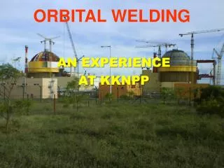
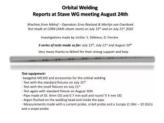
Orbital Welding Reports at Stave WG meeting August 24th Machine from Nikhef – Operators Erno Roeland & Martijn van Overbeek Test made at CERN (AMS cleam room) on July 15 th and on July 21 st 2010. Investigations made by UniGe : S. Débieux , D. Ferrère.

E N D
Orbital Welding Reports at Stave WG meeting August 24th Machine from Nikhef – Operators ErnoRoeland & Martijn van Overbeek Test made at CERN (AMS cleam room) on July 15th and on July 21st 2010 Investigations made by UniGe: S. Débieux, D. Ferrère 3 series of tests made so far: July 15th, July 21st and August 10th Very many thanks to Nikhef for their strong support and help • Test equipment: • Swagelok MS100 and accessories for the orbital welding • Test with the standard fixtures on July 15th • Test with the small fixtures on July 21st • Test again with standard fixture on August 10th • Pipe made of SS: 4mm OD and 0.7 mm wall and round Ti 4 mm OD. • Argon flushed on the welding head and inside the pipe • Measurements made with a current probe, a Hall probe and a 1scope (1 GHz – 10 GS/s) and a scope probe
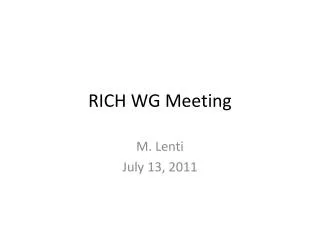
Fixtures used for the tests “Small” fixture with micro-weld head “Standard” fixture with normal weld head “Standard” fixture with SS-pipe of 4mm OD
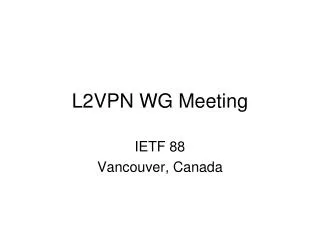
Few pictures of the set-up Welding parameters
Few pictures during the measurements Hall probe position
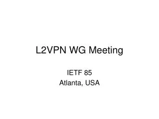
Test sequences –Scope Traces (Standard Fixture) +/- 150 mA T cycle: 150 µs Current probe trace (5A/V) Hall probe trace
Test sequences –Scope Traces (Small Fixture) Scope probe
Test sequences - 3rd series of tests on August 10th Small fixture measurements could not reproduce what was measured the 1st time!
Test sequences - 3rd series of tests on August 10th Normal fixture measurements could not reproduce what was measured the 1st time!
Summary • What have we learnt? • When something is measured the current pulse and undershoot can be as high as 25A and is happening inside 10ns during a power glitch. • Otherwise during the welding revolution and for ~20s there is a periodic current measure with up to 150mA peak and at a period of 150 µs. • When measuring the voltage across the pipe one measured a high induced voltage in the scope probe and as high as 320V peak to peak! • The 3rd series of tests were supposed to learn us more but were confusing • Unfortunately /fortunately all the measurements made with both fixtures did not show high current as the 1st times • Identification after discussion: • The glitches we measured are significant even if the current probe we used has a bandwidth of 15MHz (ok for rise time of ~20ns) • G. Blanchot from PH-ESE suspect a capacitive inductance link to the power cord of the welder • When the probe was left far from the pipe nothing was measured • One may now suspect that the long power supply cord of the head coming from the welder may have been laid differently at the 3rd series of test • Given what is said in 4) the pipe may work as an antenna • Can the glitch be more destructive than the small current pulses seen over the 20s?
Future List of tests potentially interesting to investigate: • Use a current probe with higher bandwidth (100 MHz) like the TCP312. BUT possible only for pipe lower than 3.5mm OD • Orientation and positioning of probe has to be part of the future tests relative to the welder power cord • Use high bandwidth near field probes from ETS LINGREN (G. Blanchot agreed to lend us the equipment). Can measure H and E field within 3GHz bandwidth. • Use an amplifier with one of the input set to a long wire laid along the pipe or set in different positions. • Try to use FEI4 mounted on PCB and laid on top of the pipe during OW. Make full FE characterization after each series of tests. • Ideally it would be nice to have the OW machine at CERN or to make the investigation at Nikhef by local staff. It is estimated that many iterations are needed. Input for discussion: • Test program can be long until one can certify that there is no risk to do OW with FEI4 modules in vicinity. 1 to 2 years investigation without any guaranty on the results! • As soon as something is wrong or destroyed it could certainly be a show stopper! • If everything goes fine what next to qualify? • Can an ageing be accelerated when doing a welding and how to evaluate it? • One think that the surrounding of the module/stave can change the conclusion and induce field that may be generated by the flex, the tape or the wings. Final qualification has to be done on a real stave. Is this conceivable?
Implications • Stave design include todays 2 options: • Have the stave built with 7m long pipes (capillary on 1 side) and hold inside a long jig that will permanently be attached until the integration to the beam pipe. It require that there is no show stop all along the stave loading steps: loading, wire bonding, metrology, electrical testing, thermal cycling … • Have a reduce length to ~1.2 m stave and make the orbital welding just before or after the integration • UniGe has though that modular pipe could be an alternative: • Pro: Pipe may then be glued at the latest after the integration to the beam pipe • Cons: This is purely conceptual and it really needs some time for investigation to qualify the thermal performance, the material budget, … CFRP CFRP Airex Airex PocoFoam TPG