Download
1 / 69
810 likes | 1.33k Vues
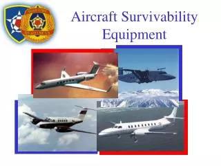
Aircraft Survivability Equipment (ASE). Aircraft Survivability Equipment (ASE). AN/APR 39A(V)1 RADAR SIGNAL DECTEOR. M-130 GENERAL DISPENSOR. AN/APX-100(V)1 MARK VII IFF. AN/ ALQ-144A (V)1. TSEC/KY58. REFRENCES. -10 Manual TM 11-5841-294-12, AN/APR-39A(V)1 TM 9-1095-206-23&P, M130

E N D
Aircraft Survivability Equipment(ASE) • AN/APR 39A(V)1 RADAR SIGNAL DECTEOR. • M-130 GENERAL DISPENSOR. • AN/APX-100(V)1 MARK VII IFF. • AN/ ALQ-144A (V)1. • TSEC/KY58
REFRENCES • -10 Manual • TM 11-5841-294-12, AN/APR-39A(V)1 • TM 9-1095-206-23&P, M130 • TM 11-5865-200-12, AN/ALQ144A(V)1 • DOD AIMS 86-100A MODE 4 Handbook • TM 11-5810-262-10, TSEC/KY58
AN/APR-39A(V)1 RADAR SIGNAL DECTEOR. • Upgraded version of the APR39(V)1 utilizes a digital processor, alphanumeric display and synthetic voice warning for radar directed airdefense threat systems.
OFP SHOULD BE THE MOST UP-TO-DATE • MDS SHOULD BE CORRECT FOR THE AREA / UNIT / MISSION OFP VERSION NUMBER 020.9 023.9 MDS VERSION NUMBER 018 041
MDS STATUS & AVAILABILITY • MDS # REGION COMMENTS • 000 EAST MED (LOW) TBD • 100 EAST MED (HIGH) TBD • 018 PERSIAN GULF OBSOLETE • 025 SOUTHCOM OBSOLETE • 027 NTC OBSOLETE. • 030 PERSIAN GULF FIELDED • 034 YUGOSLAVIA FIELDED JAN 96 • 040 KOREA (LOW) FIELDED JUL 96 • 041 KOREA (LOW) IN TESTING. TO BE FIELDED APR 98 • 140 KOREA (HIGH) FIELDED SEP 96 • 141 KOREA (HIGH) IN TESTING. TO BE FIELDED APR 98 • 051 SOUTHCOM (LOW) FIELDED MAR 97
MDS STATUS AND AVAILABILITY • MDS #REGIONCOMMENTS • 151 SOUTHCOM (HIGH) FIELDED MAR 97 • 060 CUBA (LOW) FIELDED AUG 97 • 160 CUBA (HIGH) IN WORK. TO BE FIELDED APR 98 • 070 IRAQ (LOW) IN WORK. TO BE FIELDED MAY 98 • 170 IRAQ (HIGH) IN WORK. TO BE FIELDED JUN 98 • 080 IRAN (LOW) IN WORK. TO BE FIELDED JUL 98 • 180 IRAN (HIGH) IN WORK. TO BE FIELDED AUG 98 • 090 AFRICA (LOW) TBD • 190 AFRICA (HIGH) TBD • 960 NTC (INTERIM) FIELDED. • 961 NTC IN TESTING. TO BE FIELDED APR 98
How do I employ it? • Much different than AN/ APR39(V)1 • “+” symbol not in middle • “+” symbol flashing, Degraded system performance • No synthetic voice, OK read indicator display • More than 7 targets being recognized
AN/APR-39A(V)1 COCKPIT DISPLAYS • NAMESYMBOL AUDIO AVAILABLE • GUN YES • ZSU YES • TWO 2 NO • THREE 3 NO • FOUR 4 YES • FIVE 5 NO • SIX 6 YES • SEVEN 7 NO • DIAMOND NO • DOT NO • UNKNOWN U YES • MISSILE YES
6 4 AN/APR-39A(V)1 • MOST USED DISPLAY (GHOSTING) U
AVIATOR KNEEBOARD CARDS • DEVELOPED AS MISSION PLANNING/INFLIGHT AID FOR PILOTS • MDS VERSION-SPECIFIC • LISTS EACH EMITTER AND POSSIBLE SYMBOLS
UNCLASSIFIED UNCLASSIFIED AN/APR-39A(V)1 MDS 513, LAKE MICHIGAN, 4 FEB 1997 LOW ALTITUDE ONLY AN/APR-39A(V)1 MDS 513, LAKE MICHIGAN, 4 FEB 1997 LOW ALTITUDE ONLY PRI THREAT SYMBOL(S) 1 AAA GUN DISH TV 2 SAM LAND ROLL IS 3 SAM DOG BREATH CA 4 SAM ROLAND IS 5 AAA BIG WHEEL AL 6 AAA SKYGUARD ME 7 SAM FLAP WHEEL ME 8 SAM DING DONG ME 9 SAM AN/MPQ-88 CA 10 P-51 MEADOW LARK UN NOTES: 1. (U) AN/AAR-47 MISSILE WARNING SYSTEM (MWS). IF THE MWS IS INTEGRATED WITH THE AN/APR-39A(V)1 RSDS ON YOUR AIRCRAFT, UPON MWS DETECTION OF A MISSILE LAUNCH, THE RSDS WILL DISPLAY THE “SPADE” SYMBOL ENCLOSED BY A FLASHING BOX -- IN ADDITION TO ANY OTHER THREAT SYMBOLS (RF AND/OR LASER THREATS) SHOWN. 2. (U) AN/AVR-2 OR -2A(V) LASER DETECTING SET (LDS). IF THE LDS IS INTEGRATED WITH THE AN/APR-39A(V)1 RSDS ON YOUR AIRCRAFT, UPON LDS DETECTION OF A LASER SIGNAL, THE RSDS WILL DISPLAY ONE OF THE FOLLOWING SYMBOLS -- IN ADDITION TO ANY OTHER THREAT SYMBOLS SHOWN: LASER BEAMRIDER LASER DESIGNATOR LASER RANGEFINDER 5 5 5 5 9 5 5 5 1 * * * UNCLASSIFIED UNCLASSIFIED PAGE 2 OF 2 PAGE 1 OF 2 KNEEBOARD CARD
M-130 GENERAL DISPENSOR • Provides effective survival counter-measures against most radar guided weapon systems threats
Electronics Module Controls Set controls 1-1-4-2
Preflight? SAFETY PIN • Visual inspection for loose fasteners, mounting bolts and electrical connections. • Ensure that the number of flares in the payload module corresponds to the number of flares shown in the DCP counter • Confirm chaff-flare selector switch in the dispenser assembly is set to Chaff.
CHAFF PROGRAM SELECTION • Confirm chaff program is set to 1-1-4-2 • These settings are standard and apply to all radar threats
“Before Taxi” safety pin is removed • Aircraft commander is responsible for arming system after takeoff • MAN-PRGM switch is MAN • Then go to ARM • MAN-PRGM switch to PRGM
How do I employ it? • Pilot depresses chaff firing switch, cannot be programmed to automatically fire. • Radar weapon system Tracks or when missile launch is detected on AN/APR39A(V)1
NOTE: MUST be in the PRGM position to fire the selected chaff program. • Execute evasive maneuver (mask)
Landing • Before Landing Check Mission equipment SAFE • Reinstall safety pin during “parking and shutdown, step 8”
AN/APX-100(V)1MARK VII IFF. • Provides automatic radar identification • 5 MODES of operation
MARK XII CAPABILITIES • Returns a coded reply to (SIF) using modes 1, 2, 3/A and C and provides Mode 4 identification friend or foe (IFF). • Mode 4 is secure mode of identification. • SIF Modes 1 and 2 used by military. • Modes 3/A and C used by civilian and military ATC.
What do I look for on preflight? • Loaded KIT-1C • Starting procedures
TRANSPONDER CHARACTERISTICS • The investigation into the F-15 shootdown or Army Blackhawk helicopters determined design characteristics which could present HAZARDOUS OPERATIONAL IMPLICATIONS. • Associated with the use of the AUDIO/LIGHT/OUT SWITCH • ANTENNA SELECT SWITCH
AUDIO/OUT/LIGHT SWITCH • Controls the ALERT INDICATORS for MODE 4 OPERATIONS. • AUDIO POSITION enables AUDIO TONE and REPLY LIGHT • COMPATIBLE CODES. A Green reply light indicates Friendly IFF response • VALID CODES. A Non Response will be indicated by a 400 Hz Tone
MODE FUNCTION(STANDBY POSITION) • Only when COMPATIBLE CODES are used by the interrogator. • IFF CAUTION LIGHT illuminates
AUDIO SWITCH (OUT POSITION) • Disables • Mode 4 REPLY LIGHT • Mode 4 AUDIO TONE • PRESS-TO-TEST Mode 4 REPLY LIGHT • IFF CAUTION LIGHT
AUDIO SWITCH (LIGHT POSITION) • Mode 4 REPLY LIGHT enabled • MODE 4 AUDIO tone is disabled • IFF RESPONSE. The green REPLY LIGHT will illuminate to indicate IFF was given • NON RESPONSE to IFF will not be indicated by the 400 Hz AUDIO TONE
NOTE: PLACE THE AUDIO/LIGHT/OUT SWITCH IN THEAUDIO POSITION DURING FLIGHT OPERATIONS. DO NOT USE THE OUTPOSITION
ANTENNA SELECT SWITCH(TOP, BOT, & DIV) • TOP - The transponder will respond to interrogations from that antenna • BOTTOM (BOT) - Responses allowed from the bottom antenna • DIVERSITY (DIV) - The transponder will respond through the antenna receiving the STRONGEST SIGNAL
DIV POSITION • Place the TOP/BOT/DIV switch in the DIV position during flight operations. • Do not use the TOP or BOT position. • This does not preclude using the TOP or BOT switch position for ground-based system checks.
MODE 4 ON/OUT SWITCH • MODE 4 ON/OUT SWITCH IN THE OUT POSTION • ALL AUDIO AND VISUAL INDICATIONS CEASE ( IN COCKPIT & IFF RESPONSES) • IFF CAUTION LIGHT ILLUMINATES WITH THE FREQUENCY OF “COMPATIBLE” INTERROGATIONS.
MODE 4 IFF • Normal, ON & Audio position • IFF response • COMPATABLE • Reply light • NO RESPONSE • VALID • 400 Hz tone
Formation Flight • Only one aircraft in a formation should have the transponder on • two or more aircraft operating in close proximity of one another in NORMAL ON may simultaneous attempt to respond to interrogations. The two transmitters may overkey one another, destroying the encrypted coded 3-pulse reply, this is called TONE BLANKING. The aircrew will not beware of this condition because the non-response 400 Hz tone will not be heard
IFF CAUTION • Unkeyed, (lose the key) • Kit-1C malfunction (KIT LT) • RCVR/XMTR low power, -flicker- • STBY * (compatible codes only), -flicker-
AN/ ALQ-144A (V)1 • an active, continuously operating omnidirectional, IR jammer system for helicopters, designed to confuse or decoy threat IR missile systems.
What does it do for me? • The AN/ALQ-144A(V) is designed to provide jamming of all known threat IR missile systems, and it must be operated on an aircraft equipped with low reflective paint and engine exhaust suppressers
What do I look for on preflight? • External Structure • Covert Windows • Connectors • Air Inlet