Download
1 / 15
160 likes | 370 Vues
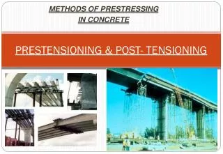
Behaviors of Post-Tensioning and Anchorage Systems. REU student: Geoff Madrazo PI’s: Dr. Richard Sause and Dr. James Ricles Graduate Mentor: David Roke ATLSS Center, Lehigh University. Overview. Introduction Purpose Objectives Methods and Materials Results Conclusion. Introduction.

E N D
Behaviors of Post-Tensioning and Anchorage Systems REU student: Geoff Madrazo PI’s: Dr. Richard Sause and Dr. James Ricles Graduate Mentor: David Roke ATLSS Center, Lehigh University
Overview • Introduction • Purpose • Objectives • Methods and Materials • Results • Conclusion
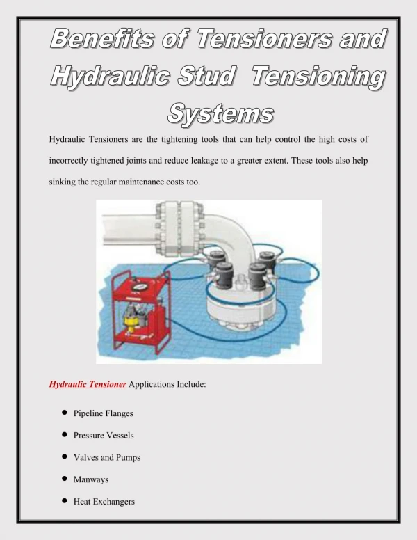
Introduction • What is post-tensioning? • Used as reinforcement for structural components. • Prestressing structural elements increases their tensile strength. Figure 1 Concrete slab under loading Source: Post-Tensioning Institute
Structural elements that use post-tensioning: Many types of bridges Elevated slabs Foundations Walls and columns Introduction Figure 2 Post-tensioned highway overpass Source: Charlie
Purpose • Acquire helpful data on the strength and behaviors of post-tensioning and anchor systems • Produce a useful reference for future works which implement post-tensioning
Objectives • Test and analyze the PT strand and anchor system • Observe and understand behaviors of the anchorage system as documented by Dr. Maria Garlock • Find practical scope of use for the strand and anchor in future projects
Methods and Materials anchor plate wedges PT strand Figure 3 Anchorage components Source: DSI Figure 4 Cross-section of anchorage Source: Williams Form Engineering Corp
PT strand - ASTM A416 7-wire treated carbon steel Min. TY (yield) = 52.74 kips Min. TU (breaking) = 58.60 kips Anchors - ACI code Guaranteed up to 95% of the breaking strength TU Methods and Materials Figures 5 and 6 Wedges and strand Source: Williams Form Engineering Corp
Static loading tests 2 part wedge vs. 3 part wedge Stress testing Tensile tests Wirelock Copper plates Methods and Materials Figure 7 Wirelock compound Source: Millfield Group
Results – So far • Static loading tests - Table 1 Test data
Results High TU Avg. TU Low TU Min. TY - 52.74 kips Figure 8 Stress-strain curve
Results Figure 9 Two-wedge vs. three-wedge plot
Conclusions • The anchorage system can not be relied upon to the 95% TU (breaking strength) • The PT strand and anchors consistently exceed the yield strength of the strand • Three-part wedges perform better under higher loads than two-part wedges
Conclusions • There doesn’t appear to be any correlation between the elongation rate (or load rate) and the breaking strength • For the Self-Centering Damage-Free Seismic-Resistant Steel Frame Systems project, it is reasonable to design past the yielding of the strands
Acknowledgements David Roke Dr. Sause Dr. Ricles John Hoffner Gene Matlock Dr. Eric Kauffman Chad Kusko ATLSS NEES NSF