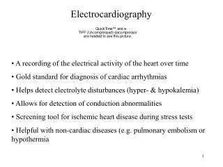
Basic Electrocardiography
"I do not imagine that electrocardiography is likely to find any very extensive use in the hospital. It can at most be of rare and occasional use to afford a record of some rare anomaly of cardiac action.Augustus D. WallerBarker LF: Electrocardiography and phonocardiography: A collective rev

Basic Electrocardiography
E N D
Presentation Transcript
1. Basic Electrocardiography Dr. Mark O�Neill
Senior Lecturer and Consultant Cardiologist
Imperial College Healthcare NHS Trust
2. "I do not imagine that electrocardiography is likely to find any very extensive use in the hospital. It can at most be of rare and occasional use to afford a record of some rare anomaly of cardiac action.�
Augustus D. Waller
Barker LF: Electrocardiography and phonocardiography: A collective review. Bull Johns Hopkins Hosp 1910;21:358�359 Initially, Waller had said "I do not imagine that electrocardiography is likely to find any very extensive use in the hospital. It can at most be of rare and occasional use to afford a record of some rare anomaly of cardiac action."11 No doubt, his continued usage of the modality caused him to change his mind because in 1917, just six years after expressing this sentiment, Waller presented before the Physiological Society of London a paper entitled "A Preliminary Survey of 2,000 Electrocardiograms."12 Initially, Waller had said "I do not imagine that electrocardiography is likely to find any very extensive use in the hospital. It can at most be of rare and occasional use to afford a record of some rare anomaly of cardiac action."11 No doubt, his continued usage of the modality caused him to change his mind because in 1917, just six years after expressing this sentiment, Waller presented before the Physiological Society of London a paper entitled "A Preliminary Survey of 2,000 Electrocardiograms."12
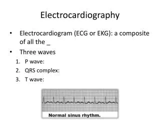
3. Outline Common Problems with ECG recording
Interpreting the 12 lead ECG
Key Diagnosis using ECGs
Interpreting 24 hour ECGs
4. Problems with ECG recording Patient identity
Lead position
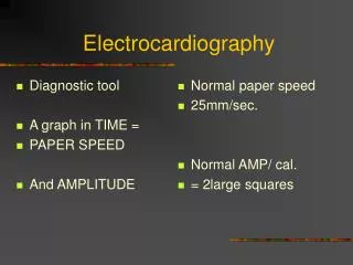
Paper speed and amplification
Artifact
Misinterpretation is much more common than poor recording technique.
5. Patient Identity
6. Lead Position There are three of these leads which are usually designated as I, II and III.
They are all bipolar (i.e., they detect a change in electric potential between two points) and detect an electrical potential change in the frontal plane.
Lead I is between the right arm and left arm electrodes, the left arm being positive.
Lead II is between the right arm and left leg electrodes, the left leg being positive.
Lead III is between the left arm and left leg electrodes, the left leg again being positive. The same three leads that form the standard leads also form the three unipolar leads known as the augmented leads. These three leads are referred to as aVR (right arm), aVL (left arm) and aVF (left leg) and also record a change in electric potential in the frontal plane.
These leads are unipolar in that they measure the electric potential at one point with respect to a null point (one which doesn't register any significant variation in electric potential during contraction of the heart).
This null point is obtained for each lead by adding the potential from the other two leads. For example, in lead aVR, the electric potential of the right arm is compared to a null point which is obtained by adding together the potential of lead aVL and lead aVF.There are three of these leads which are usually designated as I, II and III.
They are all bipolar (i.e., they detect a change in electric potential between two points) and detect an electrical potential change in the frontal plane.
Lead I is between the right arm and left arm electrodes, the left arm being positive.
Lead II is between the right arm and left leg electrodes, the left leg being positive.
Lead III is between the left arm and left leg electrodes, the left leg again being positive. The same three leads that form the standard leads also form the three unipolar leads known as the augmented leads. These three leads are referred to as aVR (right arm), aVL (left arm) and aVF (left leg) and also record a change in electric potential in the frontal plane.
These leads are unipolar in that they measure the electric potential at one point with respect to a null point (one which doesn't register any significant variation in electric potential during contraction of the heart).
This null point is obtained for each lead by adding the potential from the other two leads. For example, in lead aVR, the electric potential of the right arm is compared to a null point which is obtained by adding together the potential of lead aVL and lead aVF.
7. Paper Speed and Amplification
8. Paper Speed
9. Signal Amplification
10. Artifact
11. Artifact
13. Look at all the leads
14. Interpreting the 12 lead ECG There are 2 critical types of information to be gleaned from the ECG
The sequence of Cardiac Electrical Activation i.e. electrical recording reflecting electrical phenomena
The anatomy/geography of the abnormality
Localising conduction disturbance (accurate)
Localising perfusion disturbance (less accurate, because it is not a �perfusion recording�)
15. Cardiac Activation sequence
16. The �poor man�s� guide
17. Interpreting the 12 Lead ECG
18. Key Diagnoses using 12 lead ECG Conduction Disturbance
2nd Degree AV block
3rd Degree AV block
Arrhythmias
Atrial fibrillation
Broad Complex vs Narrow complex tachycardia
Acute Myocardial ischaemia
19. Conduction Disturbance Sinoatrial node
Failure of impulse initiation
Sinus node arrest
Atrioventricular node
Intermittent failure of impulse conduction
Ist and 2nd Degree AV block
Complete failure of impulse conduction
3rd Degree AV block
20. Where is the Conduction Problem?
21. 1st Degree AV block
22. 2nd Degree AV block
23. 2nd Degree AV block
24. 2nd Degree AV block
25. 3rd Degree AV Block
26. Atrial Fibrillation Predominantly of left atrial origin
High rate of atrial activation (>300bpm)
IRREGULAR VENTRICULAR RESPONSE
Filtering effect of the AV node
Protects the ventricle from high atrial rates
Explains why we �rate control� AF
27. Atrial Fibrillation
28. Atrial Fibrillation
29. Atrial Flutter
30. Narrow Complex Tachycardia
31. Narrow Complex tachycardia
32. Ventricular (Broad Complex) Tachycardia
33. Broad Complex Tachycardia
34. Interpreting 24 hour ECGs You have only 2 leads
They are not the same as the leads recorded with a 12 lead machine
Artifact is very common
Morphology of ST segments counts for nothing
The majority of 24h tapes are normal!
35. Lead Positions
37. Occasionally interesting!
38. What is this?
39. Summary All information is in front of you on the recording
Take a logical and structured approach to the recording
If in doubt, ask a colleague � it�s what I do