Download
1 / 44
760 likes | 1.41k Vues
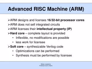
Advanced RISC Machine (ARM). ARM designs and licenses 16/32-bit processor cores ARM does not sell integrated circuits ARM licenses their intellectual property (IP) Hard core – complete layout is provided Inflexible, no modifications are possible less work for licensee

E N D
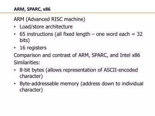
Slides created by: Professor Ian G. Harris Advanced RISC Machine (ARM) • ARM designs and licenses 16/32-bit processor cores • ARM does not sell integrated circuits • ARM licenses their intellectual property (IP) • Hard core – complete layout is provided • Inflexible, no modifications are possible • less work for licensee • Soft core – synthesizable Verilog code • Optimizations can be performed • Synthesis must be performed by licensee
Slides created by: Professor Ian G. Harris ARM-based Processors ARM Processor Core Internal Bus Peripherals Memory I/O • ARM provides the processor core • Licensee designs the remainder of the system
Slides created by: Professor Ian G. Harris TI Stellaris LM3S6965 • Nested Vector Interrupt Controller (NVIC) • Memory Protection Unit (MPU) • Other components are outside core
Slides created by: Professor Ian G. Harris ARM Processor Families • “Classic” = old • “Embedded” = low end • “Application” = high end ARM marketing material
Slides created by: Professor Ian G. Harris ARM Processor Families • Cortex-M Series • Low-cost, embedded applications • Cortex-R Series • Designed for real-time embedded apps • Faster than Cortex M • Cortex-A Series • Highest performance, made for an OS • Designed for user-facing applications • SecureCore Series • Security functionality, not clearly specified • FPGA Core • Cortex-M1 mapped to FPGAs
Slides created by: Professor Ian G. Harris Some Optional ARM Features • Memory Protection Unit (MPU) • Provides protected access to physical memory • Important to support multiple processes • Nested Vector Interrupt Controller (NVIC) • Supports interrupt nesting • Prioritized interrupts • Jazelle Direct Bytecode Execution (DBX) • Java bytecode executed directly on processor • Effectively, a new instruction set • On-chip Debug Support • CoreSight System Trace Macrocells • Debugging information extracted on-the-fly
Exceptions • Exceptions in ARM are similar to interrupts • Exception handlers must be defined for each exception • When exception occurs, processor mode is changed appropriately • Each processor mode has registers which are accessed only in that mode • Low-level security feature Slides created by: Professor Ian G. Harris
Processor Modes • Six operating modes: • • User(unprivileged mode under which most tasks run) • • FIQ (entered when a high priority (fast) interrupt is raised) • • IRQ(entered when a low priority (normal) interrupt is raised) • • Supervisor(entered on reset and when a Software Interrupt instruction is executed) • • Abort(used to handle memory access violations) • • Undef(used to handle undefined instructions) • ARM Architecture Version 4 adds a seventh mode: • • System(privileged mode using the same registers as user mode) Slides created by: Professor Ian G. Harris
Registers • General-Purpose Registers • R0 – R7 are unbanked registers, same in all modes • R8 – R14 are banked registers, different for each mode • R13 is normally the Stack Pointer • R14 is the Link Register • Return address of a subroutine call is here • R15 is the Program Counter (PC) • Program Status Registers • Current Program Status Register (CPSR) • Saved Program Status Register (SPSR) – holds value of CPSR before exception Slides created by: Professor Ian G. Harris
Instruction Sets • ARM Instruction Set • Standard 32-bit instructions • Thumb Instruction Set • 16-bit instructions • Less robust, better code density • Dynamically switch between ARM and Thumb mode • T bit in CPSR • Thumb-2 Instruction Set • 16-bit and 32-bit instructions • No switch between ARM/Thumb needed Slides created by: Professor Ian G. Harris
Thumb vs. ARM • Thumb instructions access only a subset of general-purpose registers • R0 – R7, only 3 bits needed • Branches are short range • Conditional branches offset is only 8-bits long • Instructions have fewer argument options • ADDS $r1, $r1, $r0 • ADD $r1, $r0 • No shift option on arithmetic instructions • Generally, more Thumb is more RISC than CISC Slides created by: Professor Ian G. Harris
_____ _______ __ ________ __ _____ Slides created by: Professor Ian G. Harris ARM Instruction Set • An instruction set is the set of all machine instructions supported by the architecture • Load-Store Architecture • Data processing occurs in registers • Load and store instructions move data between memory and registers • [] indicate an address • Ex. LDR r0, [r1] moves data into r0 from memory at address in r1 • STR r0, [r1] moves data from r0 into memory at address in r1
_____ _______ __ ________ __ _____ Slides created by: Professor Ian G. Harris Data Processing Instructions • Move Instructions • MOV r0, r1 moves the contents of r1 into r0 • MOV r0, #3 moves the number 3 into r0 • Shift Instructions – inputs to operations can be shifted • MOV r0, r1, LSL #2 moves (r1 << 2) into r0 • MOV r0, r1, ASR #2 moves (r1 >> 2) into r0, sign extend • Arithmetic Instructions • ADD r3, r4, r5 places (r4 + r5) in r3
Slides created by: Professor Ian G. Harris Condition Flags • Current Program Status Register (CPSR) contains the status of comparison instructions and some arithmetic instructions • N – negative, Z – zero, C – unsigned carry, V – overflow, Q - saturation • Flags are set as a result of a comparison instruction or an arithmetic instruction with an 'S' suffix • Ex. CMP r0, r1 – sets status bits as a result of (r0 – r1) • ADDS r0, r1, r2 – r0 = r1 + r2 and status bits set • ADD r0, r1, r2 – r0 = r1 + r2 but no status bits set
Slides created by: Professor Ian G. Harris Conditional Execution • All ARM instructions can be executed conditionally based on the CPSR register • Appropriate condition suffix needs to be added to the instruction • NE – not equal, EQ – equal, CC – less than (unsigned), LT less than (signed) • Ex. CMP r0, r1 • ADDNE r3, r4, r5 • BCC test • ADDNE is executed if r0 not equal to r1 • BCC is executed if r0 is less than r1
Benefits of Conditional Exec. GCD Example • Greatest Common Divisor algorithm, between r0 and r1 • Subtract smaller from larger until they are equal • Explicit branch instructions are not needed (as often) Slides created by: Professor Ian G. Harris
Higher Code Density “Normal” Assembler gcd: cmp r0, r1 ;reached the end? beq stop blt less ;if r0 < r1 sub r0, r0, r1 ;subtract r1 from r0 balgcd less: sub r1, r1, r0 ;subtract r0 from r1 balgcd stop: ARM Conditional Assembler gcd: cmp r0, r1 ; compare r0 and r1 subgt r0, r0, r1 ;subtract r1 from r0 sublt r1, r1, r0 ;else subtract r0 from r1 bnegcd ;reached the end? Slides created by: Professor Ian G. Harris
Endianess in ARM • The ARM can be set up to access its data in either little or big endian format. • Little endian: • Least significant byte of a word is stored in bits 0-7 of an addressed word. • Big endian: • Least significant byte of a word is stored in bits 24-31 of an addressed word. • This has no real relevance unless data is stored as words and then accessed in smaller sized quantities (halfwords or bytes). Slides created by: Professor Ian G. Harris
Efficient Coding • Important to be efficient in programming • RAM, FLASH, performance • Efficient C coding may require an understanding of the compiler • Compiler can erase your efficiencies for you • In the worst case, you can modify/write the assembly by hand Slides created by: Professor Ian G. Harris
_____ _______ __ ________ __ _____ Slides created by: Professor Ian G. Harris Adding Contents of an Array • Program computes the sum of the first 64 elts in the data array • Variable i is declared as a char to save space int checksum_v1 (int *data) { char i; int sum=0; for (i=0; i<64; i++) { sum += data[i]; } return sum; } • i always less than 8 bits long • May use less register space and/or stack space • i as a char does NOT save any space • All stack entries and registers are 32 bits long
_____ _______ __ ________ __ _____ Slides created by: Professor Ian G. Harris Loops, Fixed Iterations • A lot of time is spent in loops • Loops are a common target for optimization checksum_v1: MOV r2, #0 ; sum = 0 MOV r1, #0 ; i = 0 checksum_v1_loop: LDRSH r3, [r0], #4 ; r3 = *(data++) ADD r1, r1, #1 ; r1 = i+1 CMP r1, #0x40 ; compare i, 64 ADD r2, r3, r2 ; sum += r3 BCC checksum_v1_loop ; if i<64 goto loop MOV pc, r14 ; return sum • 3 instructions implement loop: add, compare, branch • Replace them with: subtract/compare, branch • Result of the subtract can be used to set condition flags
_____ _______ __ ________ __ _____ Slides created by: Professor Ian G. Harris Condensing a Loop • Current loop counts up from 0 to 64 • i is compared to 64 to check for loop termination • Optimized loop can count down from 64 to 0 • i does not need to be explicitly compared to 0 • Add the 'S' suffix to the subtract so is sets condition flags • Ex. SUBS r1, r1, #1 • BNE loop • BNE checks Zero flag in CPSR • No need for a compare instruction
_____ _______ __ ________ __ _____ Slides created by: Professor Ian G. Harris Loops, Counting Down checksum: MOV r2, r0 ; r2 = data MOV r0, #0 ; sum = 0 MOV r1, #0x40 ; i = 64 checksum_loop: LDR r3, [r2], #4 ; r3 = *(data++) SUBS r1, r1, #1 ; i-- and set flags ADD r0, r3, r0 ; sum += r3 BCC checksum_loop ; if i!=0 goto loop MOV pc, r14 ; return sum • One comparison instruction removed from inside the loop • 25% less work in loop • Possible because ARM always compares to 0
_____ _______ __ ________ __ _____ Slides created by: Professor Ian G. Harris Loop Unrolling • Loop overhead is the performance cost of implementing the loop • Ex. SUBS, BCC • For ARM, overhead is 4 clock cycles • SUBS = 1 clk, BCC = 3 clks • Overhead can be avoided by unrolling the loop • Repeating the loop body many times • Fixed iteration loops, unrolling can reduce overhead to 0 • Variable iteration loops, overhead is greatly reduced
_____ _______ __ ________ __ _____ Slides created by: Professor Ian G. Harris Unrolling, Fixed Iterations checksum MOV r2, r0 ; r2 = data MOV r0, #0 ; sum = 0 MOV r1, #0x40 ; i = 32 checksum_loop SUBS r1, r1, #1 ; i-- and set flags LDR r3, [r2], #4 ; r3 = *(data++) ADD r0, r3, r0 ; sum += r3 LDR r3, [r2], #4 ; r3 = *(data++) ADD r0, r3, r0 ; sum += r3 BCC checksum_loop ; if i!=0 goto loop MOV pc, r14 ; return sum • Only 32 iterations needed, loop body duplicated • Loop overhead cut in half
_____ _______ __ ________ __ _____ Slides created by: Professor Ian G. Harris Unrolling Side Effects Advantages: • Reduces loop overhead, improves performance • Disadvantages: • Increases code size • Displaces lines from the instruction cache • Degraded cache performance may offset gains
_____ _______ __ ________ __ _____ Slides created by: Professor Ian G. Harris Register Allocation • Compiler must choose registers to hold all data used • - i, data[i], sum, etc. • If number of vars > number of registers, stack must be used • - very slow • Try to keep number of local variables small • - approximately 12 available registers in ARM • - 16 total registers but some may be used (SP, PC, etc.)
_____ _______ __ ________ __ _____ Slides created by: Professor Ian G. Harris Function Calls, Arguments • ARM passes the first 4 arguments through r0, r1, r2, and r3 • Stack is only used if 5 or more arguments are used • Keep number of arguments <= 4 • Arguments can be merged into structures which are passed by reference float distance (point *a, point *b) { float t1, t2; t1 = (a->x – b->x)^2; t2 =(a->y – b->y)^2; return(sqrt(t1 + t2)); } typedefstruct { float x; float y; float z; } Point; • Pass two pointers rather than six floats
_____ _______ __ ________ __ _____ Slides created by: Professor Ian G. Harris Preserving Registers • Caller must preserve registers that the callee might corrupt • Registers are preserved by writing them to memory and reading them back later • Example: • Function foo() calls function bar() • Both foo() and bar() use r4 and r5 • Before the call, foo() writes registers to memory (STR) • After the call, foo() reads memory back (LDR) • If foo() and bar() are in different .c files, compiler will preserve all corruptible registers • If foo() and bar() are in the same file, compiler will only save corrupted registers
Slides created by: Professor Ian G. Harris Booting a System • Starting the OS (if there is one) or the application • Different for embedded vs. standard computers • In a simple system there may be very little to do • Just jump to the application • Having a boot process creates some uniformity to the system state • Code must exist in ROM (or flash, EEPROM)
Slides created by: Professor Ian G. Harris Bootloader, Embedded • Small program, first thing executed • Main function is to allow the flash to be reprogrammed • Not the HW method (i.e. JTAG) • Enables firmware updates • Must interact with data interfaces to receive flash data (USB, ethernet, etc.) • Starts execution of application • May also copy application to SRAM
Slides created by: Professor Ian G. Harris Bootloader Requirements • Ability to switch operating mode • Writing flash may not be possible in user mode • Access communication interfaces • Parse an executable format • S-Records, COFF, Intel, etc. • Read/Write flash and EEPROM • Compute a checksum of the application • Code security (if available)
Slides created by: Professor Ian G. Harris Typical Control Flow Enter Bootloader? Execute Application N Jump Y N Command Received? Initialize Execute Command Y • Start by checking for bootloader entrance • May be connected to an input pin • Initialize system, service commands, start application • Use jump/branch to enter bootloaderduring application
Slides created by: Professor Ian G. Harris Initialization, Commands • Initialize a minimum subset of peripherals needed to perform bootloader tasks • System clocks, ISRs, communications • Self-contained vs. Command-based • Self-containedbootloader takes no commands • i.e. Booting from an SD card • Command-based receives commands from outside • PC-based application, or networked app.
Slides created by: Professor Ian G. Harris Standard Commands • Minimum set • Erase Flash • Write Flash • Restart – Soft reset, enter application code • Common set • Unlock Flash – enter security key to get write access • Lock Flash • Erase/Read/Write EEPROM • Read Flash – Verify that the image is correct • Image Checksum – Compute checksum of application
Slides created by: Professor Ian G. Harris Memory Partitioning • Flash must be partitioned into at least 2 sections, bootloader section and application section • Partitioning features often built into the processor • Bootloader must be aware of the flash memory map • Must know where application should be loaded • Must know where bootloader is for firmware updates • Know the properties of the flash memory • Smallest erasable chunk size (4kB) • Smallest writable chunk size (8 bytes) • Flash write protection may be provided • No accidental (or intentional) overwrite
Slides created by: Professor Ian G. Harris ATmegaBootloader Support • Read-While-Write Self Programming – Can read one section of flash while writing to another section • Ex. Read the Bootloader code while writing the application • Bootloader can write entire flash, including the bootloader • Region of flash is dedicated to the bootloader • Bootloader section of memory can be resized with the BOOTSZ fuses • Lock bits used to protect flash memory
Slides created by: Professor Ian G. Harris Flash Sections • Application Section - Application code goes here • Boot Loader Section (BLS)– Bootloader goes here • Relative sizes defined by fuses BOOTSZ1, 0
Slides created by: Professor Ian G. Harris Accessing Flash • LPM – Load Program Memory (read) • SPM – Store Program Memory (write) • SPM instruction only works if issued from the Boot Loader Section • Application cannot write to flash • Access allowed depends on the protection used
Slides created by: Professor Ian G. Harris Flash Memory Protection • Boot Lock Bits (BLB) 0, 1 determine protection for application section and BLS, respectively.
Slides created by: Professor Ian G. Harris Read-While-Write • Flash is divided into Read-While-Write (RWW) and No-Read-While-Write (NRWW) • Not the same as BLS vs. Application sections • When erasing or writing a page located inside the RWW section, the NRWW section can be read during the operation • When erasing or writing a page located inside the NRWW section, the CPU is halted during the entire operation • Bootloader is always in the NRWW section
Slides created by: Professor Ian G. Harris Booting a PC • More complicated and more standardized • Must start an operating system, may give a choice • Execution starts with the Basic Input/Output System (BIOS) • Like a complicated version of the bootloader for an embedded system • Bootloader is invoked by the BIOS
Slides created by: Professor Ian G. Harris Tasks of the BIOS • Power-on self-test (POST) • Detect and execute video card’s BIOS • Detect and execute other device’s BIOS • Display start-up screen • Memory test • Set memory/drive parameters • Configure Plug and Play Devices: PCIe, USB, SATA, SPI • Assign resources (DMA channels and IRQs) • Identify boot device, load Master Boot Record (MBR) • Bootloader is in MBR
Slides created by: Professor Ian G. Harris BootloaderExample • GRUB (Grand Unified Boot Loader) • MBR contains GRUB Stage 1 • Search through partition table for Volume Boot Record for the current partition • GRUB Stage 2 in VBR • GRUB Stage 2 • Present user with choice of OS to load • Load selected kernel and run kernel