Download
1 / 16
160 likes | 188 Vues
Millimetre wave frequency band as a candidate spectrum for 5G<br>Millimetre wave frequency band as a candidate spectrum for 5G<br>Millimetre wave frequency band as a candidate spectrum for 5G

E N D
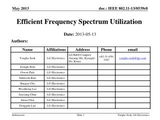
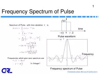
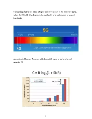
5G is anticipated to use adopt a higher carrier frequency in the mm-wave band, within the 20 to 90 GHz, thanks to the availability of a vast amount of unused bandwidth. According to Shannon Theorem, wide bandwidth leads to higher channel capacity [1]. 1
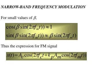
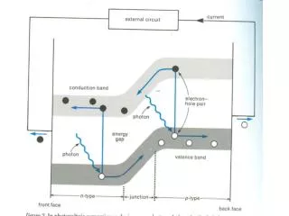
Nevertheless, there’re several challenges for 5G communication. Firstly, high path loss. The definition of LOS (light of sight) and NLOS (none light of sight) is as shown below: And the formulas are as follow [1]: Where fc is the frequency in GHz. 2
With identical distance, the path loss at 28 GHz is higher than 2.8 GHz and 800 MHz. Apparently, due to high frequency in mm-wave, high path loss is inevitable [2]. 3
Secondly, compared to conventional RF bands, mm-wave bands suffer from atmospheric attenuation very much [1]. This is because mm-wave energy is absorbed by oxygen molecules and water vapor in the atmosphere. 4
Thirdly, in mm-wave bands, the characteristics of building, such as materials and thickness, have a major impact on the level of penetration loss. This is because of their short wavelengths of the mm-wave signals. 5
Fourthly, foliage loss is a major mm-wave impairment, causing severe signal scattering in the presence of foliage [1,2]. . For example, the foliage loss at 28 GHz and 73 GHz for a penetration of 5m foliage is around 11 and 15 dB respectively, with the difference about 4 dB. It’s worth mentioning that the difference is not identical at greater foliage depths. Since the formula has a nonlinear relationship, which increases dramatically as foliage depth increases [1]. 6
Fifthly, mm-wave signals suffer from significant attenuation in heavy rain since raindrops are comparable size to mm-wave wavelength, and consequently cause high signal scattering [1]. Apparently, at the same frequency, high rain rate (heavy rain) leads to large rain attenuation. To be brief, there’re five main challenges during mm-wave signals propagation: 1. High path loss 2. High atmospheric attenuation 3. High penetration loss 4. Foliage loss 5. Rain attenuation 7
Thus, it’s anticipated that mm-wave would provide poor coverage in areas with a low density of base stations. To overcome these obstacles, one of the solutions is to reduce the Intersite-Distance (ISD), which will shorten the signal path by making the Access Point (AP) much closer to the users. With a small-cell radius below 200 m can lead to better mm-wave communication. Additionally, beamforming and larger scale antenna arrays are solutions to these obstacles as well. For mm-wave, a highly directional antenna is recommended to compensate for added losses mentioned previously thanks to its high gain, thereby ensuring reliable links for deploying 5G networks. As shown below, in theory, high gain needs large antenna dimension. However, high gain antennas can be deployed in a small physical area due to extremely small wavelength in the mm-wave band. 8
Unlike conventional cellular network planning below 3 GHz, Higher Order Sectorization (HOS) is a promising factor to improve capacity and data rate. When using antenna arrays to provide < 20 degree beam widths, HOS becomes feasible with minimal interference. 9
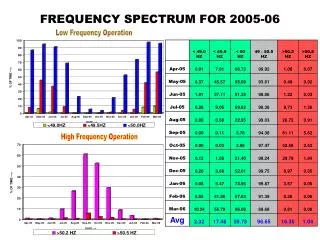
As shown below, as sectorization increases, the SINR also increases roughly. It’s worth mentioning that as sectorization increases, Inter-Cell Interference (ICI) from surrounding cells increases consequently, which would impact the coverage probability. Thus, at 10 sectors, coverage probability turns out to be lower than 8 sectors. 10
According to Shannon Theorem, higher SINR leads to higher data rate. So, as sectorization order increases, throughput increases as well. Beanforming is the concentration of power in a narrow beam width to augment gain, and supress interference efficiently. That’s why HOS becomes feasible with minimal interference. With increased gain and decreased interference, beanforming can dramatically improve the SINR, thereby leading to better network performance and higher data thoughput at the cell-edge. 11
As mentioned previously, a highly directional antenna is recommended to compensate for those added losses thanks to its high gain. To improve the gain further, antenna array is introduced to 5G application. As shown below [3], this is an antenna with 128 elements that generates four independent beams, each beam capable of a 2.5 Gbps data rate, 10 Gbps total through the array. Nevertheless, when it comes to antenna array, correlation coefficient must be taken into consideration. Correlation coefficient, ρ, is the relationship between the radiation pattern of each element in an array, which indicates how independent these elements are. To reduce the mutual coupling, the correlation coefficient between two elements is the lower the better. According to the definition, 0 ≤ ρ ≤ 1 correlation coefficient ought to be as low as zero, which indicates the two elements are independent of each other completely. 12
In terms of S-parameters, correlation coefficient can be expressed as: from the formula, we can infer that high isolation is beneficial for reduction in correlation coefficient. 13
As shown above, it’s apparently that high isolation leads to low correlation coefficient [5]. Besides, high correlation coefficient aggravates gain, thereby reducing radiation efficiency. As shown below [4]: Consequently, the element spacing has to be large enough to enable the system to avoid unwanted antenna effects, such as high correlation, high mutual coupling, changing beam patterns, and high mismatch loss. 14
As shown above, compared to conventional 0.5λ spacing, higher spacing improves the throughput. Due to shorter wavelength in mm-wave bands, higher element spacing is still realistic array size. Consequently, higher spacing of 10 to 40λ has been considered. 15
Reference [1] Millimetre wave frequency band as a candidate spectrum for 5G network architecture: A survey [2] Performances and Feasibility of mmWave Beamforming Prototype for 5G Cellular Communications [3] Fujitsu Demonstrates 28 GHz, 4-Beam, 128-Element Phased Array Antenna [4] Isolated Mode Antenna Technology for 4G [5] Novel Wideband MIMO Antennas That Can Cover the Whole LTE Spectrum in Handsets and Portable Computers 16