Download
1 / 76
1.3k likes | 4.33k Vues
The Physics of Diagnostic Ultrasound FRCR Physics Lectures. Session 1 & 2. Mark Wilson Clinical Scientist (Radiotherapy). mark.wilson@hey.nhs.uk. Hull and East Yorkshire Hospitals. NHS Trust. Session 1 Overview. Session Aims: Basic physics of sound waves

E N D
The Physics of Diagnostic UltrasoundFRCR Physics Lectures Session 1 & 2 Mark Wilson Clinical Scientist (Radiotherapy) mark.wilson@hey.nhs.uk Hull and East Yorkshire Hospitals NHS Trust
Session 1 Overview Session Aims: Basic physics of sound waves Basic principles of image formation Interactions of ultrasound waves with matter Hull and East Yorkshire Hospitals NHS Trust
Basic Physics Hull and East Yorkshire Hospitals NHS Trust
Basic Physics Wave Motion Hull and East Yorkshire Hospitals NHS Trust
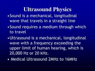
Basic Physics Sound Waves Sounds waves are mechanical pressure waves which propagate through a medium causing the particles of the medium to oscillate backward and forward The term Ultrasound refers to sound waves of such a high frequency that they are inaudible to humans Ultrasound is defined as sound waves with a frequency above 20 kHz Ultrasound frequencies used for imaging are in the range 2-15 MHz The velocity and attenuation of the ultrasound wave is strongly dependent on the properties of the medium through which it is travelling Hull and East Yorkshire Hospitals NHS Trust
Basic Physics Wave Propagation Imagine a material as an array of molecules linked by springs As an ultrasound pressure wave propagates through the medium, molecules in regions of high pressure will be pushed together (compression) whereas molecules in regions of low pressure will be pulled apart (rarefaction) As the sound wave propagates through the medium, molecules will oscillate around their equilibrium position Hull and East Yorkshire Hospitals NHS Trust
Basic Physics Power and Intensity A sound wave transports Energy through a medium from a source. Energy is measured in joules (J) The Power, P, produce by a source of sound is the rate at which it produces energy. Power is measured in watts (W) where 1 W = 1 J/s The Intensity, I, associated with a sound wave is the power per unit area. Intensity is measured in W/m2 The power and intensity associated with a wave increase with the pressure amplitude, p Power, P p Intensity, I p2 Hull and East Yorkshire Hospitals NHS Trust
Basic Physics Frequency (f): Number of cycles per second Unit: Hertz (Hz) Speed (c): Speed at which a sound wave travels is determined by the medium Unit: Metres per second (m/s) Air – 330 m/s Water – 1480 m/s Av. Tissue – 1540 m/s Bone – 3190 m/s Hull and East Yorkshire Hospitals NHS Trust
Basic Physics Wavelength (): Distance between consecutive crests or other similar points on the wave Unit: Metre (m) A wave from a source of frequency f, travelling through a medium whose speed of sound is c, has a wavelength = c / f Hull and East Yorkshire Hospitals NHS Trust
Basic Principles of Image Formation Hull and East Yorkshire Hospitals NHS Trust
Basic Principles of Image Formation D Source of sound ) Sound reflected at boundary ) ) ) ) Distance = Speed x Time 2D = c x t ) ) ) ) ) Reduced signal amplitude Pulse-Echo Principle ) ) ) ) ) No signal returns Hull and East Yorkshire Hospitals NHS Trust
Basic Principles of Image Formation Tissue 1 Tissue 2 Tissue 3 Transducer Can transmit and receive US Pulse-Echo in Tissue • Ultrasound pulse is launched into the first tissue • At tissue interface a portion of ultrasound signal is transmitted into the second tissue and a portion is reflected within the first tissue (termed an echo) • Echo signal is detected by the transducer Hull and East Yorkshire Hospitals NHS Trust
Basic Principles of Image Formation B-Mode Image A B-mode image is a cross-sectional image representing tissues and organ boundaries within the body Constructed from echoes which are generated by reflection of US waves at tissue boundaries, and scattering from small irregularities within tissues Each echo is displayed at a point in the image which corresponds to the relative position of its origin within the body The brightness of the image at each point is related to the strength (amplitude) of the echo B-mode = Brightness mode Hull and East Yorkshire Hospitals NHS Trust
Basic Principles of Image Formation Transducer B-Mode Image Formation A 2D B-mode image is formed from a large number of B-mode lines, where each line in the image is produced by a pulse echo sequence Hull and East Yorkshire Hospitals NHS Trust
Linear Phased Curvilinear Basic Principles of Image Formation Arrays Rectangular FOV Useful in applications where there is a need to image superficial areas at the same time as organs at a deeper level Trapezoidal FOV Wide FOV near transducer and even wider FOV at deeper levels Sector FOV useful for imaging heart where access is normally through a narrow acoustic window between ribs Hull and East Yorkshire Hospitals NHS Trust
Basic Principles of Image Formation B-Mode Image – How Long Does it Take? 1. Minimum time for one line = (2 x depth) / speed of sound = 2D / c seconds 2. Each frame of image contains N lines 3. Time for one frame = 2ND / c seconds E.g. D = 12 cm, c = 1540 m/s, Frame rate = 20 frames per second Frame rate = c / 2ND N = c / 2D x Frame rate = 320 lines (poor - approx half of standard TV) Additional interpolated lines are inserted between image lines to boost image quality to the human eye 4. Time is very important!!! Hull and East Yorkshire Hospitals NHS Trust
Basic Principles of Image Formation Time Gain Compensation (TGC) Deeper the source of echo Smaller signal intensity Due signal attenuation in tissue and reduction in initial US beam intensity by reflections Operator can TGC use to artificially ‘boost’ the signals from deeper tissues (like a graphic equaliser) Hull and East Yorkshire Hospitals NHS Trust
Basic Principles of Image Formation Time Transducer at fixed point Depth M-Mode Image Can be used to observe the motion of tissues (e.g. Echocardiography) One direction of display is used to represent time rather than space Hull and East Yorkshire Hospitals NHS Trust
Basic Principles of Image Formation M-Mode Image of Mitral Valve Hull and East Yorkshire Hospitals NHS Trust
Ultrasound Interactions in Matter Hull and East Yorkshire Hospitals NHS Trust
Ultrasound Interactions Reflection Scatter Refraction Attenuation and Absorption Diffraction Hull and East Yorkshire Hospitals NHS Trust
Ultrasound Interactions Atom / Molecule Speed of Sound, c The speed of propagation of a sound wave is determined by the medium it is travelling in The material properties which determine speed of sound are density, (mass per unit volume) and elasticity, k (stiffness) Bond Hull and East Yorkshire Hospitals NHS Trust
m K m K m m K Ultrasound Interactions Speed of Sound, c Consider a row of masses (molecules) linked by springs (bonds) Sound wave can be propagated along the row of masses by giving the first mass a momentary ‘push’ to the right This movement is coupled to the second mass by the spring Sound wave Hull and East Yorkshire Hospitals NHS Trust
m K m K m m K Small masses (m) model a material of low density linked by springs of high stiffness K Ultrasound Interactions Stiff spring will cause the second mass to accelerate quickly to the right and pass on the movement to the third mass Smaller masses are more easily accelerated by spring Hence, low density and high stiffness lead to high speed of sound Hull and East Yorkshire Hospitals NHS Trust
Large masses (M) model a material of high density linked by springs of low stiffness k Ultrasound Interactions M M M M k k k Weak spring will cause the second mass to accelerate relatively slowly Larger masses are more difficult to accelerate Hence, high density and low stiffness lead to low speed of sound Speed of Sound c = k / Hull and East Yorkshire Hospitals NHS Trust
Ultrasound Interactions Hull and East Yorkshire Hospitals NHS Trust
Ultrasound Interactions - Reflection Reflection of Ultrasound Waves When an ultrasound wave travelling through one type of tissue encounters an interface with a tissue with different acoustic impedance, z, some of its energy is reflected back towards the source of the wave, while the remainder is transmitted into the second tissue - Reflections occur at tissue boundaries where there is a change in acoustic impedance z2 z1 Transducer Hull and East Yorkshire Hospitals NHS Trust
m K m K m m K Ultrasound Interactions - Reflection Acoustic Impedance (z) The acoustic impedance of a medium is a measure of the response of the particles of the medium to a wave of a given pressure The acoustic impedance of a medium is again determined by its density, , and elasticity, k (stiffness) As with speed of sound, consider a row of masses (molecules) linked by springs Sound wave Hull and East Yorkshire Hospitals NHS Trust
m k m k m m k Small masses (m) model a material of low density linked by weak springs of low stiffness k Ultrasound Interactions - Reflection A given pressure is applied momentarily to the first small mass m The mass is easily accelerated to the right and its movement encounters little opposing force from the weak spring k This material has low acoustic impedance, as particle movements are relatively large in response to a given applied pressure Hull and East Yorkshire Hospitals NHS Trust
Large masses (M) model a material of high density linked by springs of high stiffness K Ultrasound Interactions - Reflection M M M M K K K In this case, the larger masses M accelerate less in response to the applied pressure Their movements are further resisted by the stiff springs This material has high acoustic impedance, as particle movements are relatively small in response to a given applied pressure Acoustic Impedance z = k Acoustic Impedance z = c Can also be shown Hull and East Yorkshire Hospitals NHS Trust
Ultrasound Interactions - Reflection z1 z2 pi , Ii pt , It pr , Ir Amplitude Reflection Coefficient (r) Z2 – Z1 pr r = = pi Z1 + Z2 Hull and East Yorkshire Hospitals NHS Trust
( ) 2 Z2 – Z1 Ir R = = Ii Z1 + Z2 Ultrasound Interactions - Reflection • Strength of reflection depends on the difference between the Z values of the two materials • Ultrasound only possible when wave propagates through materials with similar acoustic impedances – only a small amount reflected and the rest transmitted • Therefore, ultrasound not possible where air or bone interfaces are present Intensity Reflection Coefficient (R) Intensity Transmission Coefficient (T) T = 1 - R Hull and East Yorkshire Hospitals NHS Trust
Ultrasound Interactions - Reflection Hull and East Yorkshire Hospitals NHS Trust
z2 z1 i r Ultrasound Interactions - Reflection • For a flat, smooth surface the angle of reflection, r = the angle of incidence, i • In the body surfaces are not usually smooth and flat, then r i Reflection at an Angle Hull and East Yorkshire Hospitals NHS Trust
Ultrasound Interactions - Scatter Scatter Reflection occurs at large interfaces such as those between organs where there is a change in acoustic impedance Within most organs there are many small scale variations in acoustic properties which constitute small scale reflecting targets Reflection from such small targets does not follow the laws of reflection for large interfaces and is termed scattering Scattering redirects energy in all directions, but is a weak interaction compared to reflection at large interfaces Hull and East Yorkshire Hospitals NHS Trust
Ultrasound Interactions - Refraction c2 (>c1) c1 Snell’s Law Refraction When an ultrasound wave crosses a tissue boundary at an angle (non-normal incidence), where there is a change in the speed of sound c, the path of the wave is deflected as it crosses the boundary sin (i) c1 i = c2 sin (t) t Hull and East Yorkshire Hospitals NHS Trust
Ultrasound Interactions - Attenuation Intensity, I Low freq. Attenuation As an ultrasound wave propagates through a medium, the intensity reduces with distance travelled Attenuation describes the reduction in intensity with distance and includes scattering, diffraction, and absorption Attenuation increases linearly with frequency Limits frequency used – trade off between penetration depth and resolution High freq. Distance, d I = Ioe- d Where is the attenuation coefficient Hull and East Yorkshire Hospitals NHS Trust
Ultrasound Interactions - Attenuation Absorption In soft tissue most energy loss (attenuation) is due to absorption Absorption is the process by which ultrasound energy is converted to heat in the medium Absorption is responsible for tissue heating Decibel Notation Attenuation and absorption is often expressed in terms of decibels Decibel, dB = 10 log10 (I2 / I1) Hull and East Yorkshire Hospitals NHS Trust
Ultrasound Interactions - Diffraction High Divergence Aperture large compared to Low Divergence Aperture small compared to Diffraction Diffraction is the process by which the ultrasound wave diverges (spreads out) as it moves away from the source Divergence is determined by the relationship between the width of the source (aperture) and the wavelength of the wave Hull and East Yorkshire Hospitals NHS Trust
Break Hull and East Yorkshire Hospitals NHS Trust
Session 2 Overview Session Aims: Construction and operation of the ultrasound transducer Ultrasound instrumentation Ultrasound safety Hull and East Yorkshire Hospitals NHS Trust
Ultrasound Transducer Hull and East Yorkshire Hospitals NHS Trust
Ultrasound Transducer Transducer The transducer is the device that converts electrical transmission pulses into ultrasonic pulses, and ultrasonic echo pulses into electrical signals A transducer produces ultrasound pulses and detects echo signals using the piezoelectric effect The piezoelectric effect describes the interconversion of electrical and mechanical energy in certain materials If a voltage pulse is applied to a piezoelectric material, the material will expand or contract (depending on the polarity of the voltage) If a force is applied to a piezoelectric material which causes it to expand or contract (e.g. pressure wave), a voltage will be induced in the material Hull and East Yorkshire Hospitals NHS Trust
Ultrasound Transducer Transducer Hull and East Yorkshire Hospitals NHS Trust
Ultrasound Transducer Transducer A transducer only generates a useful ultrasound beam at one given frequency This frequency corresponds to a wavelength in the transducer equal to twice the thickness of the piezoelectric disk – This is due to a process known as Resonance! Choice of frequency is important – remember that attenuation increases with increasing frequency Image resolution increases with frequency Therefore, there is a trade-off between scan depth and resolution for any particular application Hull and East Yorkshire Hospitals NHS Trust
Ultrasound Transducer a NEAR FIELD FAR FIELD Beam Shape – Diffraction NFL a = radius of transducer = Wavelength Near Field Length, NFL = a2 / Hull and East Yorkshire Hospitals NHS Trust
Ultrasound Transducer Beam Shape - Diffraction In the near field region the beam energy is largely confined to the dimensions of the transducer Need to select a long near field length to achieve good resolution over the depth you wish to scan too Near field length increases with increasing transducer radius, a, and decreasing wavelength, Short wavelength means high frequency – not very penetrating Large transducer radius – Wide beam (poor lateral resolution) Trade-off between useful penetration depth and resolution!! Hull and East Yorkshire Hospitals NHS Trust
Ultrasound Transducer Beam Focusing An improvement to the overall beam width can be obtained by focusing Here the source is designed so that the waves converge towards a point in the beam, the focus, where the beam achieves its minimum width Beyond the focus, the beam diverges again but more rapidly that for an unfocused beam with the same aperture and frequency Hull and East Yorkshire Hospitals NHS Trust
Ultrasound Transducer F a W Beam Focusing Beam width at focus, W = F / a • At focal point: • Maximum ultrasound intensity • Maximum resolution Hull and East Yorkshire Hospitals NHS Trust
F Ultrasound Transducer Beam Focusing For a single element source, focusing can be achieved in one of two ways: A curved source A curved source is manufactured with a radius of curvature of F and hence produces curved wave fronts which converge at a focus F cm from the source Source Focus Hull and East Yorkshire Hospitals NHS Trust