Download
1 / 32
320 likes | 450 Vues
David Lissauer – Brookhaven National Lab. Straw man for ATLAS ID for SLHC. This layout is a result of the discussions in the GENOA ID upgrade workshop. Aim is to evolve this to include list of questions we need to address in the simulation and R&D and establish a baseline.

E N D
David Lissauer – Brookhaven National Lab. Straw man for ATLAS ID for SLHC This layout is a result of the discussions in the GENOA ID upgrade workshop. Aim is to evolve this to include list of questions we need to address in the simulation and R&D and establish a baseline
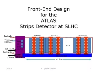
Straw man Barrel Layouts • b-layer integrated to the beam pipe. • 1 layer at R= 5 cm. • Granularity 300m x 50 m • Z 2x40 cm • Inner Layers - Pixels • 2 additional layers at R=12, 18 cm • Granularity 400m x 50 m • Z length 2x 40 cm • Middle Layers • 3 layers at R=27,38,50 cm 4 Layers (27,38,49,60) • Granularity 3.5 cm x 80 m • Z length 2x100 cm • Outer Layers • 2 Layers R= 70,95 cm 4 Layers (75,95) • Granularity 9 cm x 80 m • Z length 2x190 cm
Straw man End-cap Layouts • Discs • 7 discs • Pixel: Z= 50, 75 • SS: Z= 120,165 4 layers 120,165,180 • LS: Z= 210,260,320 • Coverage in h • Assume coverage up to 2.5 • Moderator • Left ~ 8-10 cm along the Barrel for moderator The main difference between the two options is if one has 3 or 4 SS layers and 6 or 7 Discs. This will depend at the end on the optimization of the overall detector.
Projective vs. “fixed” length Barrel • “Fixed length”: All the layers in same R region have the same length in Z. • Projective – each layer can have different length. • Projective: • Smaller Si Area • Material – needs detail engineering to comment if can be an advantage. • Fixed Length: • Easier assembly • Significant less Engineering • “Fewer” special components • e.g. fewer stave flavors. Straw man: Fixed Length Barrel
Independent vs. Integrated Pixel • Independent : Insertion “tube” as in ATLAS. • Integrated : only “b-layer” attached to beam- pipe • Independent Pixel: • Schedule of the more complicated system is decoupled from the large area detector. • Integrated Pixel: • Less material? • Services routed at lower h • Better chance for common system • One cooling system • One Heat shield Straw-man: b-layer with the beam pipe, 2,3rd layer integrated with the Barrel.
Layout Optimization Questions: • # of SS Layers: There are a number of options that need to be investigated. 3+3+4 : “Intermediate solution” 3+4+2 : Minimal solution – “robust middle section” 3+3+4 : Robust outer section. (Middle section 1D information only) • # of SS Discs: Number of Discs can vary between 6-7. Need to be matched to the Barrel. • 2D information: There is a question of how many of the layers need to have 2D information. One option is that the SS are short enough and there is no need for Z information.
ID Straw-man Layout (3 SS layers) 3 Pixel Layers 14,32,48 f Sectors 5,12,18 R Location 3 Short strip layers 22,32,40 fSectors 27,38,50 R Location 2 Long Strip layers 28,42 fSectors 70,95 R Location Moderator
ID Straw-man Layout (3 SS layers) 3 Pixel Layers 14,32,48 f Sectors 5,12,18 R Location 4 Short strip layers 22,32,40,48 fSectors 27,38,49,60 R Location 2 Long Strip layers 32,40 fSectors 75,95 R Location Moderator
Modularity – Installation Sequence • Surface Assembly of the Barrel • Assemble as much of the Barrel as possible. • In this version we assume that we can assemble part of the disks already on the surface – this needs detail Eng. Studies. • The installation sequence of ID in the pit. • Step I: Moderator and services on IWV • Step II: Barrel Surface assembly • Step III: Barrel Services (cables, pipes) • Step IV: Outer Discs • Step V: Outer Discs services • Step VI: b-layer + beam pipe
“Stave” Concept • The need for High degree of Multiplexing of power, readout etc. Lead to the concept of treating a set of modules in common. • The mechanical support can be ATLAS like support (Drums) or mechanical Stave. • For each group of modules: • power, readout, grounding “fully contained” • Service design needs to be “integrated” to the mechanical and layout. • Some of these issues are independent if it is a real or “virtual” stave. At this stage we try to propose a level of multiplexing that will allow to get an estimate for services volume and routing. The decision on the mechanical concept will have to be discussed with the engineering team that will design the mechanical structure.
SS Multiplexing • A possible multiplexing granularity is as follows: • The individual sensor module size is made of a 35x40.96 mm • A group of four individual modules are joined together to make a “super module” • A group of ~ 10 super modules are grouped together as a “stave” for multiplexing purpose. Each of the groups have self contained services: Cooling, Readout, power etc.
LS Multiplexing Concept is very similar to the SS multiplexing. The difference is mostly in the dimensions of the individual sensors.
Open System Questions. • Cooling: • Cooling System • Identical for all layers • Heat Shield • One cooling region? • Operating temperature • Identical for all layers • Support Structure • Al vs. composite material • Power Distribution: • Multiplexing schemes • DC-DC • Serial Power • Redundancy In the coming month we should collect the list of questions and possible solutions for the Engineering questions. Solutions will have to wait for detail engineering studies.
Conclusions How do we proceed?