Download
1 / 23
230 likes | 413 Vues
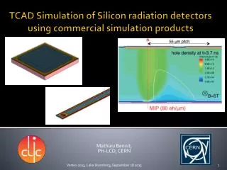
ATLAS Tracker Upgrade: Silicon Strip Detectors for the sLHC. Sergey Burdin (University of Liverpool) for ATLAS Collaboration 13th ISTC SAC Seminar "New Perspectives of High Energy Physics" 1-5 September, 2010, Novosibirsk, Russia. Upgrade Schedule.

E N D
ATLAS Tracker Upgrade: Silicon Strip Detectors for the sLHC Sergey Burdin (University of Liverpool) for ATLAS Collaboration 13th ISTC SAC Seminar "New Perspectives of High Energy Physics" 1-5 September, 2010, Novosibirsk, Russia
Upgrade Schedule S.Burdin / Atlas Tracker Upgrade
ATLAS Inner Detector Pixel (n+-on-n sensor): 3 layers+2x3 discs 1.8m2, 80M channels, 1x10¹⁵ 1MeV neq/cm2 Radiation hard technology: n+-in-n Silicon technology, operated at -6°C SCT (p+-on-n sensor): 4 layers+2x9 discs 61m2, 6.2M channels, 2x10¹⁴ 1MeV neq/cm2 p-strips in n-type silicon, operated at -7°C TRT (straw drift tubes): Barrel+2Endcaps 420K channels, 3x10¹³ 1MeV neq/cm2 Current trackers designed to survive up to 10Mrad in strip detectors ( ≤700 fb-1)
ATLAS Inner Detector Upgrade All silicon concept (no TRT) ~200m2of silicon sensors Should fit into the current ATLAS ID size Need to cope with higher radiation levels Pixels: 2.2x10¹⁶ 1MeV neq/cm2 Short Strips: 1.2x10¹⁵ 1MeV neq/cm2 Long Strips: 5.6x10¹⁴ 1MeV neq/cm2 and occupancies 3600 3000 2400 1800 1200 600 0 Much higher integrated doses (need to plan for 3000fb-1) 2030 2029 2028 2027 2026 2025 2024 2023 2022 2021 2020 2019 2018 2017 2016 2015 2014 2013 2012 2011 2010 • Should use affordable concepts in terms of technology and cost S.Burdin / Atlas Tracker Upgrade
Inner Tracker Occupancy 5 collisions (0.2 x 1034 cm-2 s-1) 400 collisions (10 x 1034 cm-2 s-1) 2.6% 1.8% 1.0% The strip occupancy should be < ~2% S.Burdin / Atlas Tracker Upgrade Short (2.4cm) and Long (9.6cm) Strip Occupancy (400/BCO)
Radiation Background Simulation Short strip Long strip Pixels n S.Burdin / Atlas Tracker Upgrade
Upgrade Inner Tracker Layout • Pixels: • 4 layers + 2x6 discs • 3.7cm≤R≤20.9cm • Strips: • Short (24mm): 3 layers • 38.0cm≤R≤62.2cm • Long (96mm): 2 layers • 74.3cm≤R≤100.0cm • 2x5 discs S.Burdin / Atlas Tracker Upgrade
P-strip vs. N-strip Readout Holes collected Deposited charge cannot reach electrode Charge spread over many strips Lower signal Electron collected Higher mobility and ~33% smaller trapping constant Deposited charge can reach electrode Qtc Q0exp(-tc/ttr), 1/ttr = bF. tC is collection “time”, ttr is effective trapping time Effect of trapping on the Charge Collection Efficiency (CCE) “New” n-in-p geometry “New” n-in-n geometry ( after type inversion) “Standard” p-in-n geometry (after type inversion) n+ p+ e- Un-depleted p- p- h+ Un-depleted p+ n+ Type inversion turns lightly doped material to “p” type 8 A. Affolder - PSD08, 1st-5th September 2008, Glasgow, Scotland S.Burdin / Atlas Tracker Upgrade
Selection of Silicon Sensors S.Burdin / Atlas Tracker Upgrade
Motivations for P-type Silicon Wafers Starting with a p--type substrate offers the advantages of single-sided processing while keeping n+-side read-out: • Processing Costs (~50% cheaper). • Greater potential choice of suppliers. • High fields always on the same side. • Easy of handling during testing. • No delicate back-side implanted structures to be considered in module design or mechanical assembly. • So far, capacitively coupled, polysilicon • biased p-type devices fabricated to • ATLAS provided mask designs by: • Micron Semiconductor (UK) Ltd • CiS Erfurt (Germany) • CNM Barcelona (Spain) • ITC Trento (Italy) • Hamamatsu Photonics HPK (Japan) • (Including full-size 10cm ×10cm prototype) S.Burdin / Atlas Tracker Upgrade Phil Allport (University of Liverpool)
n-in-p Planar FZ Irradiations 900V Strip Doses 500V Signal size thought to require soft/quenched charge multiplication Pixel Doses Radiation Fluence (1014neq/cm2) 11 S.Burdin / Atlas Tracker Upgrade
Full-size Detector Testing LivWiik (Uni Freiburg) • ATLAS07 • Full-size prototype sensors • 9.75cm x 9.75cm • 4 rows of 1280 strips each (2.4cm) • All tested sensors satisfied technical specs of non-irradiated sensors • Strip scans performed on 6 sensors showed no defects on 23040 strips: no pinholes, punch-through defects, shorts or openings of metal strips S.Burdin / Atlas Tracker Upgrade
Current SCT ATLAS Module Designs ATLAS Tracker Based on Barrel and Disc Supports Effectively two styles of double-sided modules (2×6cm long) each sensor ~6cm wide (768 strips of 80μm pitch per side) Hybrid cards carrying read- out chips and multilayer interconnect circuit Sensor Sensor Sensor Sensor Barrel Modules Forward Modules (Hybrid bridge above sensors) (Hybrid at module end) S.Burdin / Atlas Tracker Upgrade
Upgrade: Stave+PetalProgramme • Designed to minimise material • Requirements of automated assembly built in from the start • Compatible with current services being reused or similar services cross-section • Designs emphasises conservative assembly requirements assuming distributed production • All component independentlytestable prior to construction • Design aims to be low cost ~ 1.2 meter Carbon fiber facing Bus cable Carbon honeycomb or foam Hybrids Readout IC’s Coolant tube structure Spain: Valencia, Barcelona UK: Liverpool, RAL, Cambridge, Oxford, UCL, Sheffield, QMUL, Glasgow, ATC-Edinburgh, Lancaster Germany: Freiburg, DESY, Berlin Netherlands: NIKHEF Czech Republic: Prague USA: Brookhaven, Santa Cruz, SLAC, LBNL, Stonybrook, Yale, NYU, Duke S.Burdin / Atlas Tracker Upgrade
Stave: Hybrids glued to Sensors glued to Bus Tape glued to Cooling Substrate Glue Glue 1.2m 1.2m 1.2m S.Burdin / Atlas Tracker Upgrade
ATLAS Stave Electrical Concepts Need to bring in power at low current and high voltage but deep sub-micron ASICs operate at lower and lower voltages ... either serial powering ... or various proposals to achieve DC-DC conversion (Step down voltage at each module) S.Burdin / Atlas Tracker Upgrade
Cooling • Evaporative • Main requirements: • Evaporation temperature max. -35°C on detector. • Temperature gradient on detectors: 3°C • Total power from 80kW (startup, nominal) to 180kW (after irradiation, with safety) • About 1000 circuits • All complex items accessible at the scale of 1d • Two options: • Fluorocarbons • Long experience accumulated on the present system • CO2 • Many appealing properties: large latent heat, good heat transfer to cooling pipe wall • Experience with the LHCb VELO cooling system S.Burdin / Atlas Tracker Upgrade
Stave Metrology Cold Inlet Temperature: -33oC Warm/Cold Laser scanner BNL-Yale Warm – Cold (ΔT=54oC) No significant distortion Warm: Inlet Temperature: 21oC S.Burdin / Atlas Tracker Upgrade
Features of the Strip Super-Module Concept • Key points: • Modular concept. All the parts are decoupled from the module design and are modular. Assembled and functional modules are built and tested in early stage and will remain as built. • Full module coverage in Z (shorter barrel structure) • Rework is a strong point of the module concept –Possible up to the commissioning after integration • Design includes hybrid bridge (which could be also glued as for stave modules) • Thermal performance show a large safety regarding the thermal runaway • End insertion give flexibility for assembly & rework- Allows less commissioning steps • 1m20 or even longer stiff LS allows for simpler support structure (compared with SCT) Super-Module – 12 modules mounted on a local support End-insertion illustration on pre-assembled barrel structure KEK & University of Geneva S.Burdin / Atlas Tracker Upgrade
Hybrid Design and Fabrication from Japan Design from KEK Hybrid with a carbon bridge • FE chip performances as expected: • Gain ~ 100 mV/fc • Noise ~ 380 e- Module S.Burdin / Atlas Tracker Upgrade
Endcaps C. LacastaValencia • The petal concept follows closely the barrel stave concept • 5 discs on each endcap • 32 petals per disc • 116 chips per petal • 6 Sensor rings • 9 different hybrid types • 6 different sensor types • 3 short strip sensors • 2 medium strip sensors • 1 long strip sensors S.Burdin / Atlas Tracker Upgrade
Summary • Need to replace the ATLAS Inner Detector for SLHC upgrade • New Inner Detector will be all silicon • 4 pixel layers and 5x2 endcaps • 3 short strip layers • 2 long strip layers • 6x2 endcaps • Radiation issues at 3000fb-1 becoming close to manageable at all radii • Good performance large area sensors being manufactured by Hamamatsu • Good experience with super-module irradiation and complementary programme of hybrid, support and module development • R&D programme is progressing well and is reasonably compatible with the latest machine schedules (but time is still really tight) S.Burdin / Atlas Tracker Upgrade