Download
1 / 18
590 likes | 2k Vues
Intersection of Solids. ME 111 Engineering Drawing 2016. INTERPENETRATION OF SOLIDS. WHEN ONE SOLID PENETRATES ANOTHER SOLID THEN THEIR SURFACES INTERSECT AND AT THE JUNCTION OF INTERSECTION A TYPICAL CURVE IS FORMED, WHICH REMAINS COMMON TO BOTH SOLIDS.

E N D
Intersection of Solids ME 111 Engineering Drawing 2016
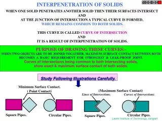
INTERPENETRATION OF SOLIDS WHEN ONE SOLID PENETRATES ANOTHER SOLID THEN THEIR SURFACES INTERSECT AND AT THE JUNCTION OF INTERSECTION A TYPICAL CURVE IS FORMED, WHICH REMAINS COMMON TO BOTH SOLIDS. THIS CURVE IS CALLED CURVE OF INTERSECTION AND IT IS A RESULT OF INTERPENETRATION OF SOLIDS. PURPOSE OF DRAWING THESE CURVES:- WHEN TWO OBJECTS ARE TO BE JOINED TOGATHER, MAXIMUM SURFACE CONTACT BETWEEN BOTH BECOMES A BASIC REQUIREMENT FOR STRONGEST & LEAK-PROOF JOINT. Curves of Intersections being common to both Intersecting solids, show exact & maximum surface contact of both solids. Study Following Illustrations Carefully. Minimum Surface Contact. ( Point Contact) (Maximum Surface Contact) Lines of Intersections. Curves of Intersections. Square Pipes. Circular Pipes. Circular Pipes. Square Pipes.
Introduction • Solids in real world in general • Combination of two or more solids • Definite curve can be seen at intersection of solids • Curve of intersection (COI) • COI is common to the intersecting solids
Cases of Intersection • The cases of intersection depend on • Type of intersecting solids, and • Manner in which they intersect. • When two solids bounded by plane surfaces such as prism and pyramid penetrate each other, we obtain straight lines as their line of intersection.
Cases of Intersection • Line of intersection between a plane surface and a curved surface of two solids such as prism and cylinder is a curve. • The line of intersection between two curved surfaces of solids such as cylinder and cone is a curve. • Manner in which solids intersect: (i) Axis perpendicular and intersecting (ii) Axis perpendicular and offset (iii) Axis inclined and intersecting (iv) Axis inclined and offset (v) Axis parallel and coinciding (vi) Axis parallel and offset
SOME ACTUAL OBJECTS ARE SHOWN, SHOWING CURVES OF INTERSECTIONS. BY WHITE ARROWS. A machine component having two intersecting cylindrical surfaces with the axis at acute angle to each other. Intersection of a Cylindrical main and Branch Pipe. An Industrial Dust collector. Intersection of two cylinders. Pump lid having shape of a hexagonal Prism and Hemi-sphere intersecting each other. Two Cylindrical surfaces. A Feeding Hopper In industry. Forged End of a Connecting Rod.
FOLLOWING CASES ARE SOLVED. REFFER ILLUSTRATIONS AND NOTE THE COMMON CONSTRUCTION FOR ALL COMMON SOLUTION STEPS One solid will be standing on HP Other will penetrate horizontally. Draw three views of standing solid. Name views as per the illustrations. Beginning with side view draw three Views of penetrating solids also. On it’s S.V. mark number of points And name those(either letters or nos.) The points which are on standard generators or edges of standing solid, ( in S.V.) can be marked on respective generators in Fv and Tv. And other points from SV should be brought to Tv first and then projecting upward To Fv. Dark and dotted line’s decision should be taken by observing side view from it’s right side as shown by arrow. Accordingly those should be joined by curvature or straight lines. Note: Incase cone is penetrating solid Side view is not necessary. Similarly in case of penetration from top it is not required. 1.CYLINDER TO CYLINDER2. 2.SQ.PRISM TO CYLINDER 3.CONE TO CYLINDER 4.TRIANGULAR PRISM TO CYLNDER 5.SQ.PRISM TO SQ.PRISM 6.SQ.PRISM TO SQ.PRISM ( SKEW POSITION) 7.SQARE PRISM TO CONE ( from top ) 8.CYLINDER TO CONE
CASE 1. CYLINDER STANDING & CYLINDER PENETRATING 2’ 1” 3” 4’ 2” 3’ 1’ 4” a’ a” h” b” b ’h’ g” c” c’g’ d” d’f’ f” a’ e” 4 3 1 2 Problem:A cylinder 50mm dia.and 70mm axis is completely penetrated by another of 40 mm dia.and 70 mm axis horizontally Both axes intersect & bisect each other. Draw projections showing curves of intersections. X Y
2’ 1” 4’ 3” 2” 3’ 4” 1’ a’ a’ a” d” b’ b’ b” d’ d’ c’ c’ c” 4 3 1 2 Problem: A cylinder 50mm dia.and 70mm axis is completely penetrated by a square prism of 25 mm sides.and 70 mm axis, horizontally. Both axes Intersect & bisect each other. All faces of prism are equally inclined to Hp. Draw projections showing curves of intersections. CASE 2. CYLINDER STANDING & SQ.PRISM PENETRATING X Y
CASE 3. CYLINDER STANDING & CONE PENETRATING 1 7’ 2 8 6’ 8’ 3 7 1’ 5’ 4 6 2’ 4’ 5 3’ Problem: A cylinder of 80 mm diameter and 100 mm axis is completely penetrated by a cone of 80 mm diameter and 120 mm long axis horizontally.Both axes intersect & bisect each other. Draw projections showing curve of intersections. X Y
1” 2’ 4’ 3” 2” 3’ 1’ 4” a’ a’ a” d” b’ b’ b” d’ d’ c’ c’ c” 4 3 1 2 Problem: A sq.prism 30 mm base sides.and 70mm axis is completely penetrated by another square prism of 25 mm sides.and 70 mm axis, horizontally. Both axes Intersects & bisect each other. All faces of prisms are equally inclined to Vp. Draw projections showing curves of intersections. CASE 4. SQ.PRISM STANDING & SQ.PRISM PENETRATING X Y
a a a 2’ 1” 4’ 3” 2” 3’ 4” 1’ b b c c d d e e f f f X Y 4 3 1 2 Problem: A cylinder 50mm dia.and 70mm axis is completely penetrated by a triangular prism of 45 mm sides.and 70 mm axis, horizontally. One flat face of prism is parallel to Vp and Contains axis of cylinder. Draw projections showing curves of intersections. CASE 5. CYLINDER STANDING & TRIANGULAR PRISM PENETRATING b e
CASE 6. SQ.PRISM STANDING & SQ.PRISM PENETRATING (300 SKEW POSITION) 1” 2’ 4’ 3” 3’ 2” 4” 1’ a” f” e” b” c” d” 4 3 1 2 Problem: A sq.prism 30 mm base sides.and 70mm axis is completely penetrated by another square prism of 25 mm side s.and 70 mm axis, horizontally. Both axes Intersect & bisect each other.Two faces of penetrating prism are 300 inclined to Hp. Draw projections showing curves of intersections. a’ f’ e’ b’ c’ d’ X 300 Y
2’ 1’ 3’ 5’ 4’ 6’ g h f 8 a 9 7 e 10 6 1 b d 2 c 5 3 4 5 mm OFF-SET CASE 7. CONE STANDING & SQ.PRISM PENETRATING (BOTH AXES VERTICAL) X Y a’ b’h’ c’g’ d’f’ e’ Problem: A cone70 mm base diameter and 90 mm axis is completely penetrated by a square prism from top with it’s axis // to cone’s axis and 5 mm away from it. a vertical plane containing both axes is parallel to Vp. Take all faces of sq.prism equally inclined to Vp. Base Side of prism is 0 mm and axis is 100 mm long. Draw projections showing curves of intersections.
Problem: A vertical cone, base diameter 75 mm and axis 100 mm long, is completely penetrated by a cylinder of 45 mm diameter. The axis of the cylinder is parallel to Hp and Vp and intersects axis of the cone at a point 28 mm above the base. Draw projections showing curves of intersection. CASE 8. CONE STANDING & CYLINDER PENETRATING 1 1 1 2 2 8, 8 2 3 7 3 3 7, 4 4 6 4 6 5 5 5 Y X g h f a e b d c o’ o” a’ b’h’ c’g’ d’f’ e’ g” g”h” a”e” b”d” c”