Progress and Specifications of the ILC Main Linac System and Cavity Production
This document details significant advancements in the International Linear Collider (ILC) project following the Global TDR event in June 2013. Key areas include the specifications of the Main Linac system, the performance of accelerating cavities, and the optimization of electron and positron sources. It outlines the cavity gradient results, production yield, and improvements in cavity design and processing methods. Challenges regarding cost reduction and reliability for long-term operation are also discussed, highlighting the ongoing efforts to refine the ILC's technological framework.

Progress and Specifications of the ILC Main Linac System and Cavity Production
E N D
Presentation Transcript
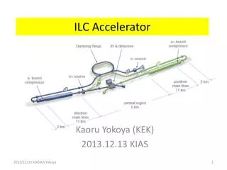
ILC Accelerator Kaoru Yokoya (KEK) 2013.12.13 KIAS
TDR • Global TDR Event on Jun.12.2013 • TokyoCERNFNAL • TDR handed to LCC Director Lyn Evans
Site Down-selection • Down selection to Kitakami site announded in August end
ILC Layout • Electron source • Positron source • Damping Rings • RTML • Main linacs • BDS
Main Linac • Key area of ILC • ~2/3 of the total cost • TDR specification • Gradient at vertical test • Average 35MV/m • Accept cavities > 35 -20% = 28MV/m • Q0 > 0.8x10¹⁰ at 35MV/m • yield > 90% (Up to 2 surface treatment passes) • Average operating gradient 31.5MV/m • Accept the range +/- 20% • Q0 > 1xx1010 at 31.5MV/m
Progress in 1.3 GHz ILC Cavity Production A. Yamamoto, May2013, ECFA13 • Progress in EXFEL (800 cavity construction as of 2012/10): (courtesy by D. Reschke: the 2nd EP at DESY) • RI: 4 reference cavities with Eacc > 28 MV/m, (~ 39 MV/m max.) • Zanon: 3 reference cavities with Eacc > 30 MV/m ( ~ 35 MV/m max.)
Global Cavity Gradient Results - EU 3 slides from R.Geng, LCWS12 DESY data, D. Reschke et al., SRF2009, TUPPO051.
Global Cavity Gradient Results - Americas JLAB data, R.L. Geng et al., IPAC2011, MOPC111.
Global Cavity Gradient Results - Asia KEK data, Y. Yamamoto et al., IPAC2012, WEPPC013.
High Gradient Accelerating Cavity > 16000 cavities needed for 500GeV Production yield: 94 % at > 28 MV/m, Achieved Average gradient: 37.1 MV/m
System Viability Proof ILC Spec: 5.8mA, 1ms DESY: FLASH • SRF-CM string + Beam, • ACC7/PXFEL1 < 32 MV/m > • 9 mA beam, 2009 • 800ms, 4.5mA beam, 2012 KEK: STF • S1-Global: complete, 2010 • Cavity string : < 26 MV/m> • Quantum Beam : 6.7 mA, 1 ms, • CM1 & beam, 2014 ~2015 FNAL: NML/ASTA • CM1 test complete • CM2 operation, in 2013 • CM2 + Beam, 2013 ~ 2014 A. Yamamoto, JPS meeting, Mar.2013
Euro-XFEL Status E.Kako, 2013/12/05, KEK
Europe - XFEL cavity production As of 11.09.2013 Num. of cavities: vendor 1 23 vendor 2 56 2nd pass: additional high-pressure rinse usable gradient: X-ray limited (dark current) Maximum gradient D. Reschke, LCWS13
US – Fermilab CM-2 CM-2 features all high gradient cavities (> 35 MV/m) Cryomodule is installed and cold. Commissioning has started – no results yet New 500 W 2K refrigerator operational M.Harrison, LCWS13
Cryomodule Production– Fermilab & JLAB High Q_0 cryomodule with reduced cryogenics operating costs: Improved cooling capability New cavity surface processing recipe Improved magnetic shielding Adiabatic cool-down process M.Harrison, LCWS13
US – LCLS II • 4 GeV CW SRF Linac based FEL based on ILC cavities at SLAC • 35 cryomodules – 280 cavities • Gradient 16 MV/m; Q0 2e10 at 1.8K • Beam power 1.2 MW max • Cryogenic power 5.5 MW • Located in the upstream end of the • existing 3km tunnel 550 m ~ LCLS-II Length L2 j = -21° V0=1447 MV Ipk = 50 A Lb = 0.56 mm L3 j = 0 V0=2409 MV Ipk = 1.0 kA Lb = 0.024 mm L0 j= * V0=97 MV Ipk = 12 A Lb = 2.0 mm L1 j =-22° V0=220 MV Ipk = 12 A Lb =2.0 mm HL j =-165° V0 =55 MV CM01 CM2,3 CM15 CM35 CM04 CM16 3.9GHz LTU E = 4.0 GeV R56 = 0 sd 0.016% 2-km LH E = 98 MeV R56 = -5 mm sd = 0.05 % BC1 E = 250 MeV R56 = -55 mm sd = 1.4 % BC2 E = 1600 MeV R56 = -60 mm sd = 0.46 % GUN 0.75 MeV 100-pC machine layout: Oct. 8, 2013; v21 ASTRA run; Bunch length Lb is FWHM Linac and compressor layout M.Harrison, LCWS13
10 year Evolution of STF at KEK up to ~ 420MeV E.Kako, 2013/12/05, KEK
Remaining Technical Issues for Main Linac • Cavity production yield as high as possible • Improvement of cavity performance in cryomodule • Finalize the coupler design (TTF3/XFEL or STF2 type) • Confirmation of the reliability in long term operation (coupler, tuner) • Further cost reduction in mass production • Higher cavity gradient for Ecm>500GeV
Positron Source 3 possible shemes of positron beam generation • Undulatormethod(adopted in ILCbaseline) • Conventional Method • Hit a few GeV electrons on a target, and collect the generated positrons • adopted in many accelerators, well established • Issues in the application to ILC • Survivability of the target OK • Emittance of the generated positron OK (improved DR optics) • Transport to DR entranceunder study • No polarized positron • Laser-Comptonmethod(far future)
ILCDesign(undulator method) • Electron energy>150GeV • Undulator • At the end of the electron linac • Helical, superconducting • Length ~150m (~230m when highly poloarized positron is needed) • K=0.92, l=1.15cm, (B=0.86T on the axis) • beam aperture 5.85mm (直径) • Target: rotating titanium alloy • Flux Concentratorfor positron capture • Normal-conducting accelkeration up to 400MeV • Polarization~30%(~60% with photon collimatorand longer undulator)
Positron Yield • UndulatoraT the end of electron l;inac • positron yield depends on the electron energy (=center-of-mass energy / 2) • Positron insufficient for Ee < 150GeV • To restore the luminosity, the electron linac is operated at 10Hz: • 5Hz for positron production • 5Hz for collision
Target • Wheel of Titanium alloy, diameter 1m • Must rotate at 100m/s (2000 rpm) in vacuum • Under test at LLNL using Ferromagnet seal • Still unsatisfactory • Outgassing spikes still being observed • More works needed • market products don’t work
Positron Capture • Baseline : Captureby flux concentrator • No change since RDR • But lower the max field5T3.5T(simulation showed sufficient) • Problem: pulse duration 1ms • Also being tested at LLNL • Can be replaced with QWT (Quarter Wave Transformer) • But requires longer undulaort (x1.6倍) • Heavier load on the target
Conventional e+ Source for ILC Normal Conducting Drive and Booster Linacs in 300 Hz operation e+ creation go to main linac 20 triplets, rep. = 300 Hz • triplet = 3 mini-trains with gaps • 44 bunches/mini-train, Tb_to_b = 6.15 n sec 2640 bunches/train, rep. = 5 Hz • Tb_to_b = 369 n sec Drive Linac Several GeV NC 300 Hz Booster Linac 5 GeV NC 300 Hz DR Tb_to_b = 6.15 n sec Target Amorphous Tungsten Pendulum or Slow Rotation 2640 bunches 60 mini-trains Time remaining for damping = 137 m sec T.Omori
Bunch Pattern Moving target still needed but much slower =132 bunches <-- the 100 ns gap is required to cure an e- cloud problem in e+ DR. T.Omori
Issues of the Positron System • Undulator Scheme • Rotating target and flux concentrator development at LLNL • Photon collimator for higher polarization • Conventional Source • “conventional” but still needs some more R&D • High current, high rep rate driver linac • Moving target (<~ 5m/s) • Flux concentrator • Overall simulation • Confirm the positron yield • Including capture, bunch compression, beamloading & energy compression • Choice of undulator/conventional will not affect the tunnel shape • The driver electron linac for Conventional Source can be installed in the space for undulator+photon drift in the ubdulator scheme • Therefore, we have some couple of years to the deadline of the choice
Moving Target • <~5m/sec required (1/20 of undulator scheme) • 2 possible schemes being developed at KEK 5Hz pendulum with bellows seal rotating target with ferromagnetic seal bellows seal air ferromagnetic fluid seal vacuum air vacuum main issue: vacuum main issue: life of bellows First step prototype being tested
Damping Rings • Requirements • gex = 5.5 mm, gey = 20nm • Time for damping 100ms • First step 1312 bunches, maximum 2625 bunches • bunch-by-bunch injection/extraction • Circumference ~3km • 1 ring for each of electron and positron in the first step • bunch interval ~6ns • (if necessary) add one more positron ring when going to 2625 bunches • depends on electron cloud • 1 electron ring in any case (bunch interval 3ns) quadrupole section dipole section
Electron Cloud Instability • Has been studied at CESR-TA by international team • Gave recommendation for the mitigation method (table below) • Arc and wiggler sections requires antichamber • Full power in 3.2km ring needs aggressive mitigation plan • No significant difference between 6.4km with 2600 bunches and 3.2km with 1300 bunches ECLOUD`10 (October 13, 2010, Cornell University)
Damping Ring Vacuum Chamber • Following the recommendation by CESR-TA team, ILC adopts the following chambers • Other instabilities are less serious in positron damping ring • FII (Fast Ion Instability) is the most important in the electron ring
BDS(Beam Delivery System) • Ultimate role of BDS is to focus the beam at the IP, but there lots of devices to do this • Machine Protection System • Tune-up/emergency dump • Collimator • Beam diagnostics section (beam energy, emittance, polarization) • Muon absorber • Crab cavity • Feedback system • Beam diagnostics after IP (beam energy, polarization) • Main beam dump
ATF2: Beam Focusing Test Facility at KEK The ATF2 has been designed, constructed and operated under the international collaboration. ATF2 DR LINAC 50 m 120 m
ATF2 Goals • Beam size at 1.3GeV • Goal 37nm • ~65nm achieved • Beam positron stabilization to a few nm by feedback
IP Feedback • Bunch interval is long enough for intra-train digital feedback • Advantage of SC collider • Large disruption parameter • Dy = 25
Issues on BDS • ATF2 • Beam focus by another factor 2 • Stabilization to ~2nm • Design check • beam dumpline • impedances • Commissioning strategy • Is the IP beam size monitor needed? • Access to IR hall • Access slope in TDR (mountain region) but, is vertical shaft possible?
Site Specific Design Kitakami-site cross section Damping Ring Detector Hall Ring To Main Linac (RTML) PM+13 PM+12 PM+10 PM-ab PM+8 e+ ML Surface Structures e- Source PM-8 Existing surface road PM-10 PM-12 (Slope <7%) PM-13 e+ Source Access Hall PX Access Tunnel (Center Campus) (Slope <10%) e- Main Linac (ML) Existing road (The background photo shows a similar site image, but not the real site.) RTML turn-around
CFS Plan Towards the Construction Start 2013 2014 2015 2016 2017 2018 2019 A.Enomoto, LCWS13
From the LCWS Conclusion on CFS • The selected site satisfies the TDR conventional designs without any fundamental issues • The remaining issues yet to be worked out (such as the path length and positron scheme) will not affect the underground construction and surface facility layout • Intensive geotechnical study of the detector hall by a Japanese company. This will be checked with the previous European IR hall analysis
LCC Pre-IL Accelerator Organization Project Management LC Project Office (KEK) Technical Board Baseline, Schedule Cost, EDMS SRF ww Accelerator Design & Integration ww Conventional Facilities ww Main Linac ww Electron Source ww Cryogenic Support Japan Beam Delivery ww Positron Source ww Safety Japan Machine-Detector Interface ww Damping Rings ww Electrical Support Japan RTML & bunch compressor ww Mechanical Support Japan Domestic Programs & System Tests Controls & Computing Japan
Summary • Site down-selected to Kitakami, Japan • Site-specific design going to start • There are some remaining issues • positron • Final focus (ATF2) • New organization under LCC-ILC box (chaired by Mike Harrison) is being formed