Finite State Machines (FSM)
110 likes | 268 Vues
This presentation provides a comprehensive overview of Finite State Machines (FSM), emphasizing their critical role in controlling sequential circuits. It discusses the essential components of FSMs, including states, transitions, inputs, outputs, and actions. A detailed example of design steps will highlight their application in real-world systems such as digital cameras and Bluetooth security. Participants will engage in exercises to solidify understanding. This material is tailored for engineering students and professionals keen on integrating FSMs in various applications.

Finite State Machines (FSM)
E N D
Presentation Transcript
Ain Shams University Faculty of Engineering Integrated Circuits Lab Finite State Machines(FSM) Presented by: Sameh Assem Ibrahim
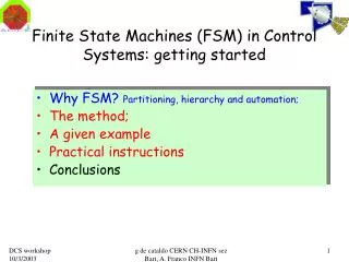
Digital Still Camera Block Diagram PC Block Diagram Bluetooth Chip • Controllers can be implemented using FSM. • They control the operation of sequential circuits. • A controller is a part of any system block diagram. • A single system may contain more than one controller. -The need for FSM -What is a FSM? (Initial Example) -FSM components -Design Steps -Implemented Example -Exercise
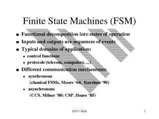
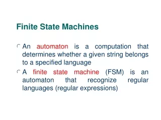
An abstract machine consisting of a set of states (including the initial state), a set of input events, a set of output events and a state transition function. The function takes the current state and an input event and returns the new set of output events and the next state. -The need for FSM -What is a FSM? (Initial Example) -FSM components -Design Steps -Implemented Example -Exercise The Fourth Year Student example
States A state represents a condition or situation during the life of a FSM during which it satisfies some condition or waits for some event. Each state represents the cumulative history of its behavior. We have 3 types of states: 1- Start state 2- Simple State 3- Idle State Transitions A state transition indicates that the FSM in the source state will perform certain specified actions and enter the destination state when a specified event occurs or when certain conditions are satisfied. A state transition is a relationship between two states. You can show one or more state transitions from a state as long as each transition is unique. Inputs Inputs are normal input signals as any VHDL entity. They are used as the control signals of the FSM. 2 input signals must be included in any FSM: 1- Clock (FSM is a sequential circuit) 2-Reset (Which initiates the operation in the start state) Events An event is an occurrence that may cause the state of a system to change; it has no duration and can precede or follow another event. An event conveys information. An event is a change in one of the input signals. Outputs These are the control signals coming out of the FSM to control the data flow in the system and to enable or disable blocks. Again they are as any output signal in a VHDL entity. Actions A “task” defined by the current state that takes place due to an event An event is a change in the outputs of the FSM. • States • Transitions • Inputs • Events • Outputs • Actions -The need for FSM -What is a FSM? (Initial Example) -FSM components -Design Steps -Implemented Example -Exercise
State State Current State Current State State FSM FSM FSM Inputs Inputs Outputs Outputs Inputs Outputs Inputs are changed (Event) Inputs are changed (Event) Current State (Transition) State Outputs are changed (Action) FSM Inputs Outputs Inputs are changed (Event) Current State (Transition) -The need for FSM -What is a FSM? (Initial Example) -FSM components -Design Steps -Implemented Example -Exercise
Determine the various states of the system. • Determine the inputs and the outputs to the FSM to obtain the required data flow and produce the required control signals. • Perform a state minimization. • Design the FSM either by writing a VHDL code or by using a state diagram editor (Renoir or HDL designer series included in FPGA Advantage) • Simulate for Verification. • Synthesize. -The need for FSM -What is a FSM? (Initial Example) -FSM components -Design Steps -Implemented Example -Exercise
SAFER+ Algorithm Controller (used in Bluetooth Security) -The need for FSM -What is a FSM? (Initial Example) -FSM components -Design Steps -Implemented Example -Exercise Block Diagram
-The need for FSM -What is a FSM? (Initial Example) -FSM components -Design Steps -Implemented Example -Exercise SAFER-Controller (FSM)
-The need for FSM -What is a FSM? (Initial Example) -FSM components -Design Steps -Implemented Example -Exercise RTL Schematic
Digital Camera -The need for FSM -What is a FSM? (Initial Example) -FSM components -Design Steps -Implemented Example -Exercise Block Diagram
-The need for FSM -What is a FSM? (Initial Example) -FSM components -Design Steps -Implemented Example -Exercise State Diagram